ELCOS- Parma- Italy - gb - DCA-110
4
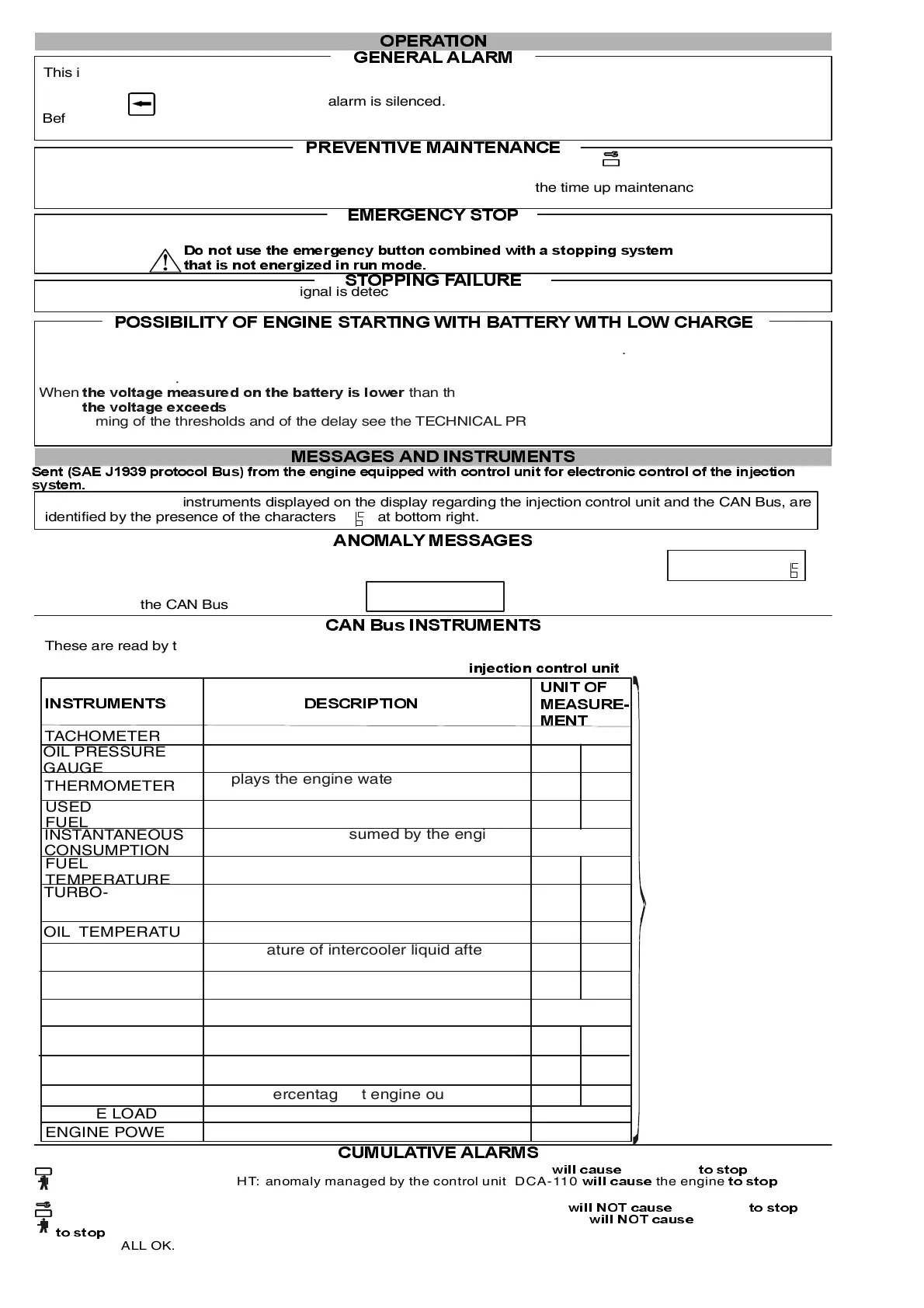
&$1%XV,167580(176
These are read by the injection control unit and shown on the display when the engine is running.
SOME MAKES OF
ENGINE DO NOT
PROVIDE FOR THE
DISPLAY OF ALL THE
LISTED INSTRUMENTS
All anomalies regarding these instruments are managed by the .
LQMHFWLRQFRQWUROXQLW
0(66$* (6$1 ',1 6758 0(176
6 HQW6$(-SURWRFRO%XVIURPWKHHQJLQHHTXLSSHGZLWKFRQWUROXQLWIRUHOHFWURQLFFRQWURORIWKHLQMHFWLRQ
V\VWHP
All the messages or instruments displayed on the display regarding the injection control unit and the CAN Bus, are
identified by the presence of the characters at bottom right.
$120$/<0(66$*(6
The anomaly messages managed by the injection control unit are indicated on the display.
SPN...............................
FMI.......... ANOMALY
CAN Bus
ANOMALY
Problems with connection to
the CAN Bus
23(5$7,2 1
*(1(5$/$/$50
This is produced by mounting an acoustic signal, linked to the appropriate terminal.
It can be arranged so that it is activated continually or for a set time.
When key is pressed the general alarm is silenced.
Before starting automatically the engine activates the intermittent general alarm for 8 seconds, followed by a pause of
3 seconds. This function can be switched off: see TECHNICAL PROGRAMMING OPERATIONS manual on page 8.
35(9(17,9(0$,17(1$1&(
When preventive maintenance operations need to be carried out, the yellow LED flashes while the number of
the intervened maintenance appears.
The timing for the maintenance operations and the procedure for zeroing the time up maintenance indication
can be programmed by the manufacturer of the engine.
(0(5* (1&<6723
The emergency stop can be activated in all working conditions, by mounting one or more click down push-button.
The stop is immediate, does enable the general alarm and EMERGENCY STOP is shown on the display.
672 33,1*)$,/85(
This intervenes if the engine running signal is detected 60 seconds after the stop command.
STOPPING FAILURE will be read on the display.
3266,%,/,7<2 )( 1* ,1 (67$5 7,1*:,7+%$77(5< :,7+ /2: &+$5* (
(with control unit in automatic mode)
Starts or stops the engine depending on the voltage measured on the battery terminals.
.
When than the minimum threshold, the engine starts.
When the maximum threshold after the intervention delay, the engine stops. To change the
programming of the thresholds and of the delay see the TECHNICAL PROGRAMMING OPERATIONS manual on
page
WKHYROWDJHPHDVXUHGRQWKHEDWWHU\LVORZ HU
WKHYROWDJHH[F HHGV
10.
Before starting automatically, the generator set activates the intermittent general alarm for 8 seconds, followed by a
pause of 3 seconds.
' RQRWXVHWKHHPHUJHQF \EXWWR QFRPELQHGZLWKD VWRSSLQJV\VW HP
WKDW LVQRWH QHUJ L]H GLQUX QPRGH
&808/$7,9($/$506
LED (red) STEADY LIGHT: anomaly managed by the injection control unit the engine .
ZLOOFDXVH WRVWRS
LED (yellow) : . STEADY LIGHT anomaly managed by the injection control unit the engine
ZLOO127FDXVH WRVWRS
LED (red) FLASHING LIGHT: anomaly managed by the control unit DCA-110
ZLOOFDXVH WRVWRS
the engine .
LED ( ) T: DCA-110
, or indicates a preventive maintenance operation.
yellow FLASHING LIGH anomaly managed by the control unit the engine
LED OFF ALL OK.
ZLOO127FDXVH
WRVWRS
,167580(176
TACHOMETER
GAUGE
THERMOMETER
USED
FUEL
CONSUMPTION
FUEL
TEMPERATURE
TURBO-
INTERCOOLER
TEMPERATURE
INTAKE
TEMPERATURE
COOLANT
LEVEL
FUEL
PRESSURE
ENGINE TORQUE
ENGINE LOAD
ENGINE POWER
81,72)
rpm
'(6&5,37,21
Displays the number of engine revolutions
Displays the pressure of the engine oil
Displays the engine water or oil
temperature
Total amount of litres of fuel used
Amount of fuel consumed by the engine
per unit of time (l/h)
Temperature of the fuel from the inlet of
the injectors
Temperature of turbocharger lubricant
Temperature of the engine lubricant oil
Temperature of intercooler liquid after
the turbocharger
Temperature of the pre-combustion air
Level of the coolant expressed in %
Pressure of the fuel between the supply
pump and the injection pump
Pressure of the liquid in the cooling
system
Torque percentage at engine outlet
Load percentage delivered by the engine
kW
%
Nm
bar
bar
kPa
kPa
%
°C °F
°F
°C
°F°C
l/h
I
°F°C
0($685(
0(17
bar kPa
CHARGER
TEMPERATURE
Torque percentage at engine outlet
°C
°F
°C °F
COOLANT
PRESSURE
 Loading...