12
COMMISIONING OF THE SYSTEM
6
6.1 Description of the supply control unit
TIME:
Lock timing adjustment
The Supply control unit includes:
Protection lid for the
connections
Protection lid for the
connections
Front lid
LED signaling of programming /
defect within the system
*PROG. : programming button
S2: existence of tension at the
+Uv - GND terminals
S1: presence of tension at the
+14V - GND terminals
*The kit does not require programming.
This button is used only if you add
additional Terminals or panels to the
system.
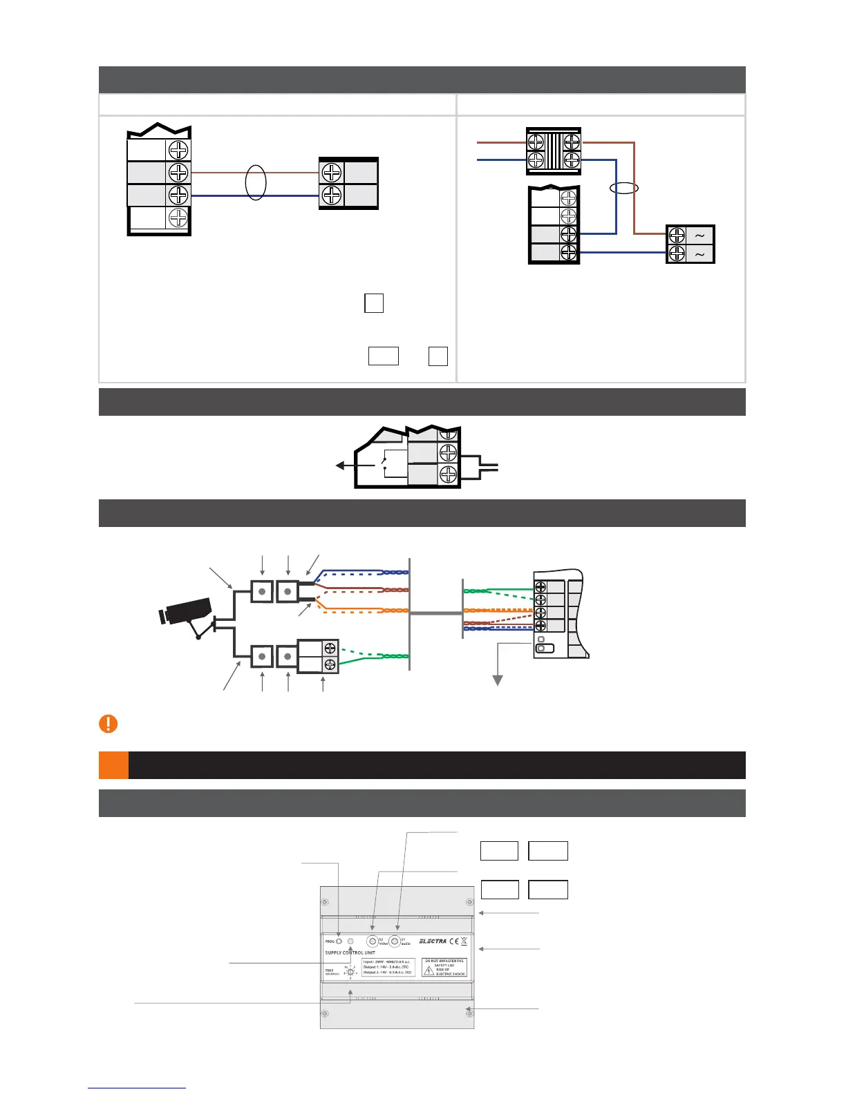
5.1 Installation of the electromagnetic lock
Direct current (DC)
Direct current
electromagnetic lock (DC)
LC2
Cable
2 x 0.75 mm
BUT
LC
LA/C
LA
Supply control unit
LC1
Cable
2 x 0.75 mm
Alternative current
electromagnetic
lock (AC)
BUT
LC
LA/C
LA
Transformer
12 V230 V AC
Supply control unit
Alternative current (AC)
Ÿ The Supply control unit can supply a current of max. 1A
for the supply of the lock.
Ÿ The tension of +14 V DC is present on the LC terminal of
the Supply control unit.
Ÿ The connection of a lock actuating button from the
interior of the building will be made at the BUT and LC
terminals of the Supply control unit.
(optional)
AC
5.3 Connection of one external video camera (optional)
External
video camera
V/(+)
Supply control unit
Jumper
G/(-)
Video Balun
BROWN
GREEN
BLUE
ORANGE
BLUE
BROWN
UTP cable
CAT 5e
Not connected - with exterior camera
ORANGE
GREEN
Core Cable (for power)
If in a system you want to install more than one External video camera, you need to connect it to the Video
Selection Box (VSB.4DN.BLW)
Coaxial Cable
(video signal)
BNC
connectors
RCA
connectors
Braid (GND)
Central Conductor
(+12V)
Maximum output current from
the Supply Control Unit to power
a video camera is of 0,4 A
Ÿ The Supply control unit can supply a
current of max. 1A for the supply of the
lock.
PROG