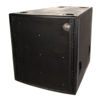
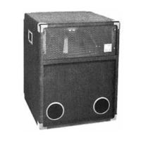
Xb Bass System
Xb Bass System
7
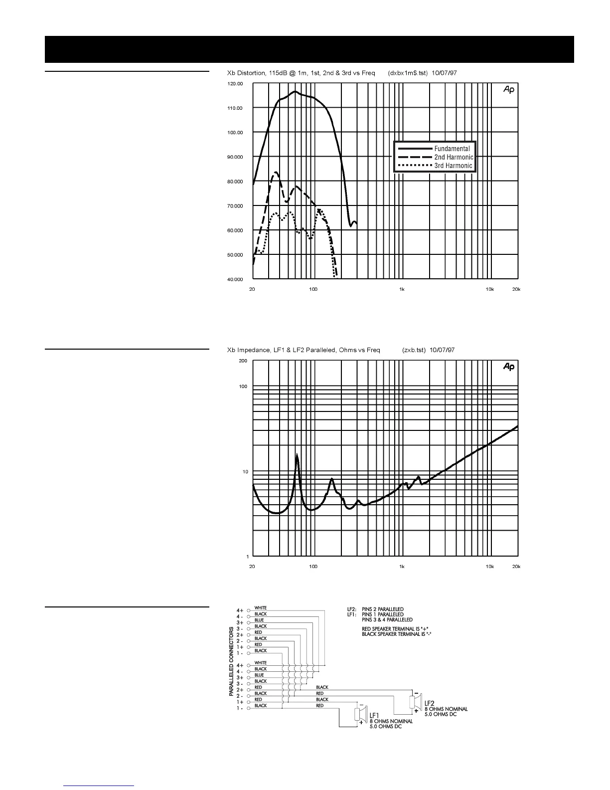
Figure 5 — Distortion
Distortion for the Xb was measured on axis
in the far field in an anechoic environment
with an input signal that would result in a
sound pressure level of 115 dB at one meter.
The Klark Teknik DN8000 digital electronic
unit was used to provide the necessary
crossover filters, equalization and time de-
lay. The sound pressure level was normal-
ized for an equivalent one-meter distance.
Plots of second and third harmonic distor-
tion are shown referenced to the funda-
mental.
Figure 6 — Impedance
The impedance of each frequency band
of the Xb was measured in an anechoic
environment
Figure 7 — Wiring Diagram
The wiring diagram of each frequency band
of the Xb is shown.