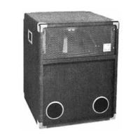
Xds Double Subwoofer System
Xds Double Subwoofer System
6
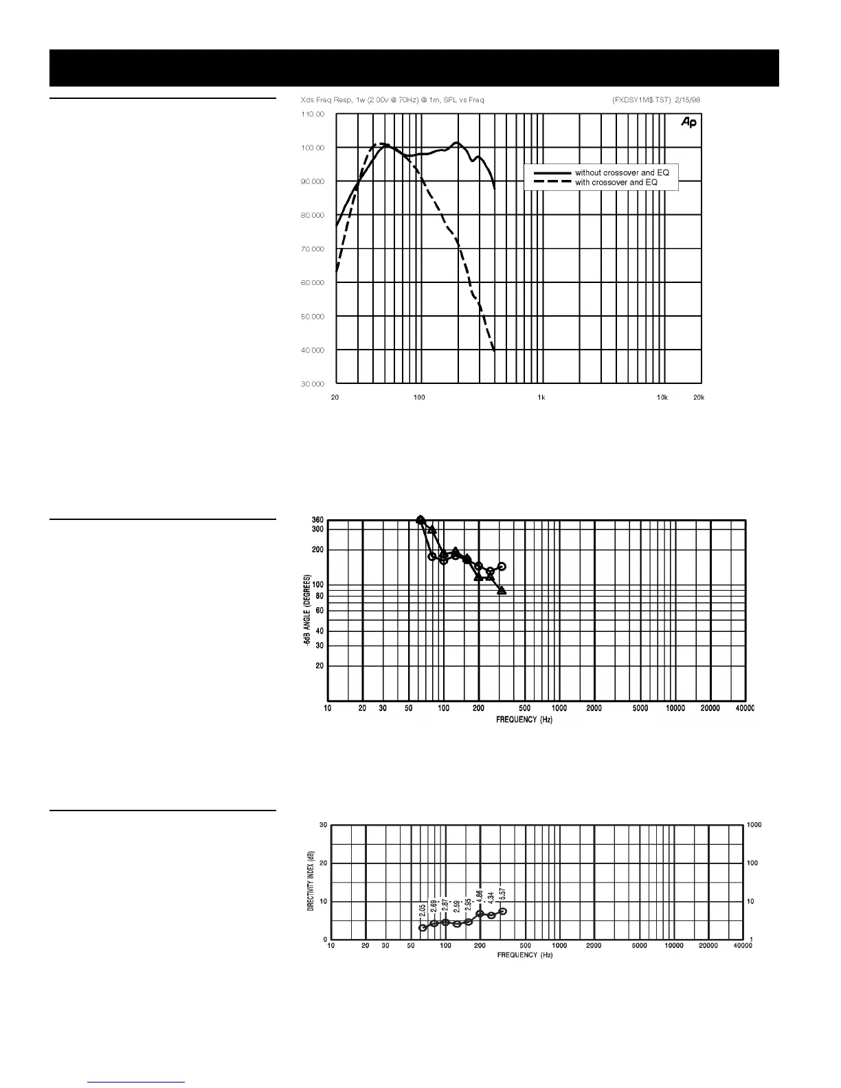
Figure 2 — Frequency Response
The frequency response of the Xds was mea-
sured on axis in the far field in an anechoic
environment using a swept sine-wave sig-
nal. The Klark Teknik DN8000 digital elec-
tronic unit was used to provide the neces-
sary crossover filters, equalization and time
delay. One watt of power (2.00-volts rms at
70 Hz) was applied to the mid band of the
low-frequency section. The sound pressure
level was normalized for an equivalent one-
meter distance.
Figure 3 — Beamwidth
The beamwidth of the Xds, (i.e., the included
horizontal and vertical coverage angles at the
-6-dB points) was measured with a full-
spherical measurement system as described
in Figure 1.
Figure 4 — Directivity
The directivity index, D
i
, and directivity fac-
tor, R
, of the Xds were measured with a full-
spherical measurement system as described
in Figure 1.