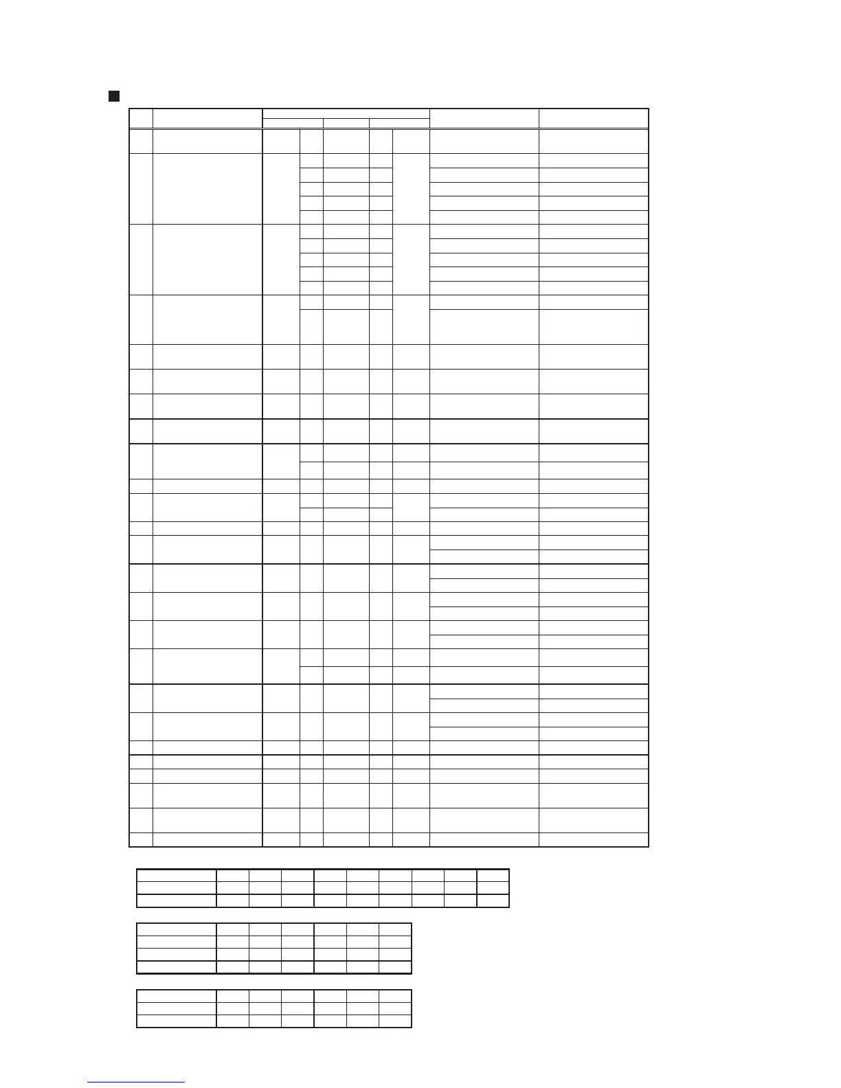
Wire color
1
Overheat Prevention
Device (Thermal Fuse)
CN10 3 W - BK 1 CN10 2 or less
23 W - O 16 DC 1 - 16 V
23 W - G 18 DC 1 - 16 V
23 W - V 20 DC 1 - 16 V
23 W - BK 24 DC 1 - 16 V
6 Y - BL 17 DC 1V or less When valve is fully open
23 W - O 25 DC 1 - 16 V
23 W - G 26 DC 1 - 16 V
23 W - V 27 DC 1 - 16 V
23 W - BK 28 DC 1 - 16 V
10 Y - BL 17 DC 1V or less When valve is fully open
3 R - BL 17 DC 14 - 16 V
5 Y - BL 17
DC 0.5 - 15 V
over 408 pulses/min.
(over 6.8Hz)
Y (+) BL (-)
5
Wate
r Inlet
Thermistor
CN63 4 W - W 2 CN63 DC 1 - 4.5 V
32 - 212°F
0 - 100°C Note 1)
6
Water Outlet
Thermistor
CN63 1 W - W 2 CN63 DC 1 - 4.5 V
32 - 212°F
0 - 100°C Note 1)
7
Heat Exchanger
Thermistor
CN63 3 W - W 2 CN63 DC 1 - 4.5 V
32 - 212°F
0 - 100°C Note 1)
8
Exhaust Thermistor
CN63 7 W - W 2 CN63 Note 2)
Note 2)
1
Flame
Rod
- DC 0.45μ A or less When no flame is detected
10 Fan Motor CN27 4 BR - BL 2 CN27 DC 7 - 45 V
1 R - BL 2 DC 10 - 14 V
3 Y - BL 2 100 Hz - 400 Hz 4 pulse/revolution
12 Igniter CN197 1 BK - BL 3 CN102 DC 14 - 16 V When igniter is sparking
DC 14 - 16 V When valve is open
19 - 31 Coil resistance
DC 14 - 16 V When valve is open
36 - 58 Coil resistance
DC 14 - 16 V When valve is open
36 - 58 Coil resistance
DC 0.3 - 15 V
50 - 80 Coil resistance
1
Flame
Rod
- DC 1μ A or more At flame detection
DC 14 - 16 V When valve is open
36 - 58 Coil resistance
DC 14 - 16 V When valve is open
36 - 58 Coil resistance
20 High Limit Switch CN10 3 W - W 12 CN10 1 or less Contact resistance
21 Air Inlet Thermistor CN63 5 W - W 2 CN63 DC 0.7 - 4.4 V Note 3)
22 Water Level Electrode CN38 31 W - BL 17 CN38 DC 14 - 16 V
-
Power Supply
(Power Circuit Board)
CN92 1 W - BK 3 CN92 AC 108 - 132 V
-
Power Supply
(Main Circuit Board)
C102 4 R - BL 3 C102 DC 14 - 16 V
- Remote Contro
ller CN89 1 BL - BL 3 CN89 DC 14 - 16 V
2
6
6
6
Fan Motor CN27
CN38
4
9
14
Circuit board Check points
CN27
Water Flow Sensor
CN78Flame Rod
CN38
Bypass Flow
Control Valve
Heat Exchanger Flow
Control Valve
CN38
CN38
RemarksNormal value
13
Primary Gas
Solenoid Valve
CN10 5 W - BL CN10
11
3
Gas Solenoid Valve - 1
16 Gas Proportioning Valve
15 Gas Solenoid Valve - 2
CN10 9
R - BL CN101CN101 7
CN10 8 GY - BL CN10
BR - BL CN10
BK - BL CN10
6
6
619 Gas Solenoid Valve - 4 CN10 7
10 O - BL CN10
17 Flame Rod CN78
18 Gas Solenoid Valve - 3 CN10
Note 1)
・
Inlet / Outlet / Heat Exchanger Thermistor Temperature Characteristics
Temperature (°F) 32 50 68 86 104 122 140 158 176
Temperature (°C) 0 10 20 30 40 50 60 70 80
Resistance (k ) 23.7 15.5 10.3 7.0 4.9 3.5 2.5 1.9 1.4
Note 2) ・Exhaust Thermistor Temperature Characteristics
Temperature (°F) -4 14 32 50 68 86
Temperature (°C) -20 -10 0 10 20 30
Resistance (k ) 487 296 162 98.3 61.4 39.5
Voltage (V) 4.6 4.3 3.9 3.4 2.8 2.3
Note 3) ・Air Inlet Thermistor Temperature Characterist
ics
Temperature (°F) -4 14 32 50 68 86
Temperature (°C) -20 -10 0 10 20 30
Resistance (k ) 106.5 59.6 34.4 20.6 12.6 8.0
The ON/OFF condition of water level electrode
can be checked using the maintenance
monitors.
When maintenance monitor number 19 reads
"000", the condition of the electrode is normal.
When this monitor reads "001", the condition of
the electrode is abnormal.
Note 4)
<EN19WI30LS, EP19WI30LS>
Note 4)
Circuit Board Checkpoints
CN38
CN38
Ω
Ω
Ω
Ω
Ω
Ω
Ω
Ω
Ω
Ω
Ω



 To Next Page