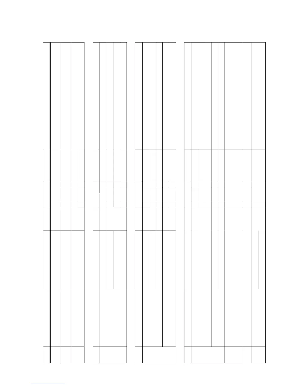
Normal Value
10kHz – 100kHz
DC0.45μA or less
BL-Burner case
BL-Electrode
1
1
2. Fan does not begin rotating when hot water is being demanded:
Normal Value
DC12.75V – 16.5V
DC14V – 16V
DC14V – 16V
DC0.3V – 15V
3
6
6
7
W-BK
W-BL
BK-BL
BL-R
1
5
9
6
3. Fan rotates normally, but no flame ignites on the burner:
Normal Value
10kHz – 100kHz
DC1μA or more
See pg. 27, 28
OFF [000]
DC0.3 – 15V
GND
F-
rod
8
BL-Burner case
BL-Electrode
BL-R
1
1
6
Normal Value
10kHz – 100kHz
DC1μA or more
See pg. 27, 28
DC0.3 – 15V
GND
F-
rod
7
BL-Burner case
BL-Electrode
BL-R
1
1
6
4. A flame ignites on the burner, but it goes out immediately:
5. Flame goes out while hot water is being supplied:
Error
Code
Possible Causes
71
70
11
11
12
35
29
94
72
Checkpoint
Error
Code
Possible Causes
Checkpoint
Error
Code
Possible Causes
Checkpoint
Error
Code
Possible Causes
Checkpoint
Check for damage to the gas valve drive
circuit on the
circuit board
.
Measure the current from the flame rod
when there is no flame.
Check for a ground fault.
Igniter failure
Check the flame rod
Check the flame rod
Check the current from the flame rod
Check for a diconnected ground from the
circuit board
Check gas supply and manifold
pressures
Check gas proportioning valve
Check maintenance monitor no. 19
Check the current from the flame rod
Check for a diconnected ground from the
circuit board
Check gas supply and manifold
pressures
Check gas proportioning valve
Check primary gas solenoid valve
Check gas solenoid valve 1
Check gas proportioning valve
Gas Valve Drive Circuit Abnormality
Ignition Failure
Flame Detecting Circuit abnormality
(initial flame fault detection)
Flame Rod Triggered
(Doesn't sense flame during operation)
Gas Supply Pressure or Manifold
Pressure Abnormality
Gas Supply Pressure or Manifold
Pressure Abnormality
Flame Rod Abnormality
(Flame detected when no flame present)
Connector No.
CN-78
CN-10
CN-197, 102
CN-101
CN-101
Connector No.
CN-78
Connector No.
CN-78
CN-101
2
W-W7
CN-63
2
W-W7
CN-63
Connector No.
Pin No. &
Code Color
Pin No. &
Code Color
Pin No. &
Code Color
Pin No. &
Code Color
How to Fix Problem and Reset Unit
Replace Igniter
How to Fix Problem and Reset Unit
Visually confir
m that a flame ignites, check wiring connections to flame rod, and
check wiring connections to gas proportioning and gas solenoid valves.
Check f
or a bad contact or a bad connection between flame rod and circuit board,
check for a ground fault in the unit, especially the circuit board ground.
Check for damage or improper connection of the ground wire between the circuit
board and the metal case of the unit.
Current value changes depending on the load.
Proportioning value resistance: 50 Ω– 90Ω.
How to Fix Problem and Reset Unit
Visually confirm that a flame ignites, check wiring connections to the flame rod,
and check wiring connections to gas proportioning and gas solenoid valves.
Check for a bad contact or a bad connection between the flame rod and
circuit board
.
Check for a ground fault in the unit, especially the
circuit board
ground.
Check that the input is proper for the load.
If no.19 is ON [111], check the following.
Check for condensate trap blockage. Check for drain pipe blockage.
Check for proper connection of condensate water level electrode.
Check for short circuit of condensate water level electrode cord.
If normal value, replace the circuit board.
Check for heat exchanger pipe clogging.
Check for heat exchanger fin blockage.
Check for intake water temperature. (too high?)
Current value changes depending on the load.
Proportioning valve resistance:
50 Ω– 90Ω.
How to Fix Problem and Reset Unit
GND
Elect-
rode
Detection of
circuit board
abnormality.
Circuit board
Abnormality
Disconnect the electrical power, then reconnect electrical power to the water heater to
reset the system. If the
circuit board
abnormality is continuous, replace the
circuit
board
.
Disconnect the electrical power, then reconnect electrical power to the water heater to
reset the system. If the error code "71" is continuous, replace the
circuit board
.
If the "72" error code is displayed, check the signal from the flame rod (also make sure
that there is not a problem with the grounding of the appliance).
If the signal is normal, replace the
circuit board
. If it is abnormal, replace the flame rod.
Current value changes depending on the load.
Proportioning value resistance: 50 Ω– 90Ω.
Check for abnormal combustion.
Check flue and air inlet for blockage or obstruction.
Check for open or short circuit,or improper connection.
Compare to temperature characteristic list on pg. 21.
Check for open or short circuit or for an improper connection.



 To Next Page