Do you have a question about the Electrolux ERF501L and is the answer not in the manual?
General safety guidelines for service engineers, including skill requirements, power disconnection, and caution with mechanical parts.
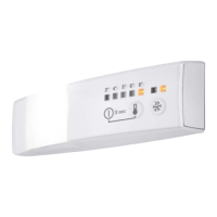
Details operating voltage, frequency range, and identifies control panel LEDs and buttons for temperature and modes.
Identifies and describes the purpose of connectors A through F on the ERF501L appliance for system connections.
Provides detailed pin assignments for J5 SUPPLY, J1 FAN DC, J4, J6, and J DAAS connectors, including diagrams.
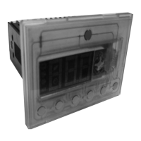
Illustrates and describes the additional fixation and fixation within the compartment for the ERF501L appliance.
Details the steps to activate service mode and explains commands like Service mode, Next, Action, and Exit service mode.
Explains AC output tests for various loads like compressors, heaters, and fans, indicating their status (on/blinking).
Details digital output tests for components like FR lamp, DC fans, and FZ lamp, showing their states (on/blinking).
Covers damper tests (local, remove) and heater tests (UI anti condensation, DC frame heater) within service mode.
Details digital input tests and temperature probe tests, showing component states and sensor activation signals.
Explains how the temperature alarm functions, including LED blinking, reset procedures, and conditions for deactivation.
Details the door alarm activation, its indicators (flashing LEDs), and the conditions under which it stops.
This document outlines the service procedures for Electrolux cold appliances equipped with an electronic control system, specifically the ERF501L model, focusing on food preservation. It serves as a service manual for qualified and authorized service engineers, providing essential information regarding the Printed Circuit Board (PCB) and its associated components. The manual emphasizes safety precautions, stating that all work inside the appliance requires specific skills and knowledge, and that the power supply must be disconnected before accessing internal components. It also advises wearing suitable protection due to potential injuries from mechanical parts.
The ERF501L appliance features two ACS power boards with an integrated user interface (UI). The UI includes temperature LEDs, a Superfrost LED, and buttons for On/Off, Temperature control, Superfrost activation, and resetting temperature alarms. The manual details the various connectors on the PCB, including those for the sidekick, user interface, DC fan, door switch, NTC sensors (for fridge and evaporator), compressor, and defrost heater. These connections are crucial for the proper functioning and control of the appliance's various systems.
The manual also covers the physical montage of the ERF501L, illustrating additional fixation points and fixation within the compartment, which are important for secure installation and stability of the electronic components.
A significant portion of the manual is dedicated to the "Service Mode LED Combinations," which is a diagnostic feature designed to assist service engineers in troubleshooting. Service mode can be initiated on both cold and warm appliances, with a specific exception for testing the digital input heater switch, which requires a cold appliance. When service mode is activated, all light indications turn on, and all components are switched off. Sensors perform self-diagnosis, while components must be checked manually. Activating a component in service mode provides electricity to it, allowing engineers to test the power supply and check for voltage absorption. This helps in identifying whether a problem lies with the motor or the power board, for instance, if the refrigerator compressor fails to activate.
To activate service mode, a specific sequence of actions must be followed: switch on the appliance, unplug it, wait 10 seconds, plug it back in, wait 6 seconds, and then press a key for 5 seconds within 6 to 16 seconds after power-on. The same key is used for all commands within service mode. Holding the key for 5 seconds within the specified timeframe enters service mode, indicated by all lights turning on. A long press moves the service mode to the next component, with lights switched off as an indicator. A short press activates or deactivates components, indicated by the light being lit when the command is applicable. Holding the key for 5 seconds exits service mode, with no indicator.
The service mode includes various tests to diagnose different parts of the appliance. The "AC output test" checks AC loads connected to the appliance, displaying only physically mounted components. When this test starts, all components are switched off. The test covers components such as the FR compressor, FZ compressor, heater, FR lamp, AC EV fan, AC FR fan, EV electro valve, AC Zero degree fan, water faucet, FZ lamp, auger motor, ice selector, AC condenser fan, perfect drawer, balance heater, frame heater, FR VCC compressor, FZ VCC compressor, and condenser electro valve. The LED indicators (on, blinking) provide feedback on the status of these components during the test.
The "Digital output test" ensures that all digital outputs connected to the electronics are automatically switched off at the start of the test. This test includes components like the FR lamp, zero degree lamp, DC EV fan, DC FR fan, DC Zero-degree fan, DC Condenser fan, FZ lamp, and DC Air filter fan, with LED indicators showing their status.
The "Damper test" checks the local damper and remove damper, indicating their status with "on" or "blinking" LEDs. The "Heater test" focuses on the UI anti-condensation heater and DC frame heater, also using LED indicators.
The "Digital input test" is designed to check various digital inputs. In this phase, the action key is not used. A light on indicates a digital input is open, while a light off indicates it is closed. This test covers the FR door, FZ door, zero degree door, heater switch, ice maker, paddle, and rapid drink cooler.
The "Temperature probe test" differs from other tests as sensors are not activated electronically by pressing a key. Instead, their activation is signaled by a yellow light that illuminates to the right. If the circuit breaker is open, this light is lit. This test checks various temperature sensors, including FR air, FZ air, FR EV, zero degree air, PB ambient, UI ambient, FZ EV, and UI ambient humidity, with LED indicators showing their status (blinking or on).
Finally, the manual addresses "Alarms ERF501L," specifically the temperature alarm and door alarm. The temperature alarm is indicated by a blinking LED when the temperature moves outside a set threshold. This LED continues to blink until the alarm is reset by pushing the Reset button for 3 seconds or until the temperature returns to within the threshold, at which point the LED turns off automatically. During a temperature alarm, no other buttons on the UI function until the alarm is reset. It's noted that Super freeze mode deactivates freezer temperature control and prevents an alarm from activating even if the temperature is outside the threshold. The door alarm activates if a door is left open for a certain period. The temperature key and set temperature LED will flash (500ms on, 500ms off). The alarm stops when the door is closed, with specific timings for fridge door (5 minutes) and freezer door (80 seconds).
| Model | ERF501L |
|---|---|
| Brand | Electrolux |
| Voltage | 220-240V |
| Frequency | 50/60Hz |
| Protection Class | IP20 |
| Type | Controller |