Do you have a question about the Electrolux ERF501L and is the answer not in the manual?
| Model | ERF501L |
|---|---|
| Brand | Electrolux |
| Voltage | 220-240V |
| Frequency | 50/60Hz |
| Protection Class | IP20 |
| Type | Controller |
General safety guidelines for service engineers, including skill requirements, power disconnection, and caution with mechanical parts.
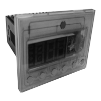
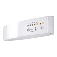
Details operating voltage, frequency range, and identifies control panel LEDs and buttons for temperature and modes.
Identifies and describes the purpose of connectors A through F on the ERF501L appliance for system connections.
Provides detailed pin assignments for J5 SUPPLY, J1 FAN DC, J4, J6, and J DAAS connectors, including diagrams.
Illustrates and describes the additional fixation and fixation within the compartment for the ERF501L appliance.
Details the steps to activate service mode and explains commands like Service mode, Next, Action, and Exit service mode.
Explains AC output tests for various loads like compressors, heaters, and fans, indicating their status (on/blinking).
Details digital output tests for components like FR lamp, DC fans, and FZ lamp, showing their states (on/blinking).
Covers damper tests (local, remove) and heater tests (UI anti condensation, DC frame heater) within service mode.
Details digital input tests and temperature probe tests, showing component states and sensor activation signals.
Explains how the temperature alarm functions, including LED blinking, reset procedures, and conditions for deactivation.
Details the door alarm activation, its indicators (flashing LEDs), and the conditions under which it stops.