40
6. As soon as refrigerant in sight glass has gone down
to predetermined level, close charging cylinder valve.
WARNING: DISCONNECT THE CHARGING
CYLINDER HEATER AT THIS TIME TO
PREVENT THE CYLINDER PRESSURE FROM
EXCEEDING ITS MAXIMUM LIMITS.
7. Allow system to sit for five minutes.
8. Turn on refrigerator compressor. Run compressor
for few minutes and monitor system pressures.
9. When satisfied that unit is operating correctly,
clamp high-side process tube with pinch-off tool
while unit is still running.
10. Slowly open high-side manifold gauge valve to
allow compressor to remove any refrigerant trapped
in high-side hose and process fitting.
11. Close both manifold gauge valves. Ifhigh-side
gauge reading rises, pinch-off must be corrected
before proceeding.
12. Remove high-side process tube adaptor and solder
process tube closed.
13. Clamp low-side process tube with pinch-off tool
while unit is running. Remove low-side process tube
adaptor and solder process tube closed.
14. Check process tubes for refrigerant leaks.
FINAL LEAK TEST
1. With refrigerator turned OFF, leak test all low-side
system components.
2. Turn unit ON and run until condenser is warm. Leak
test high-side system components.
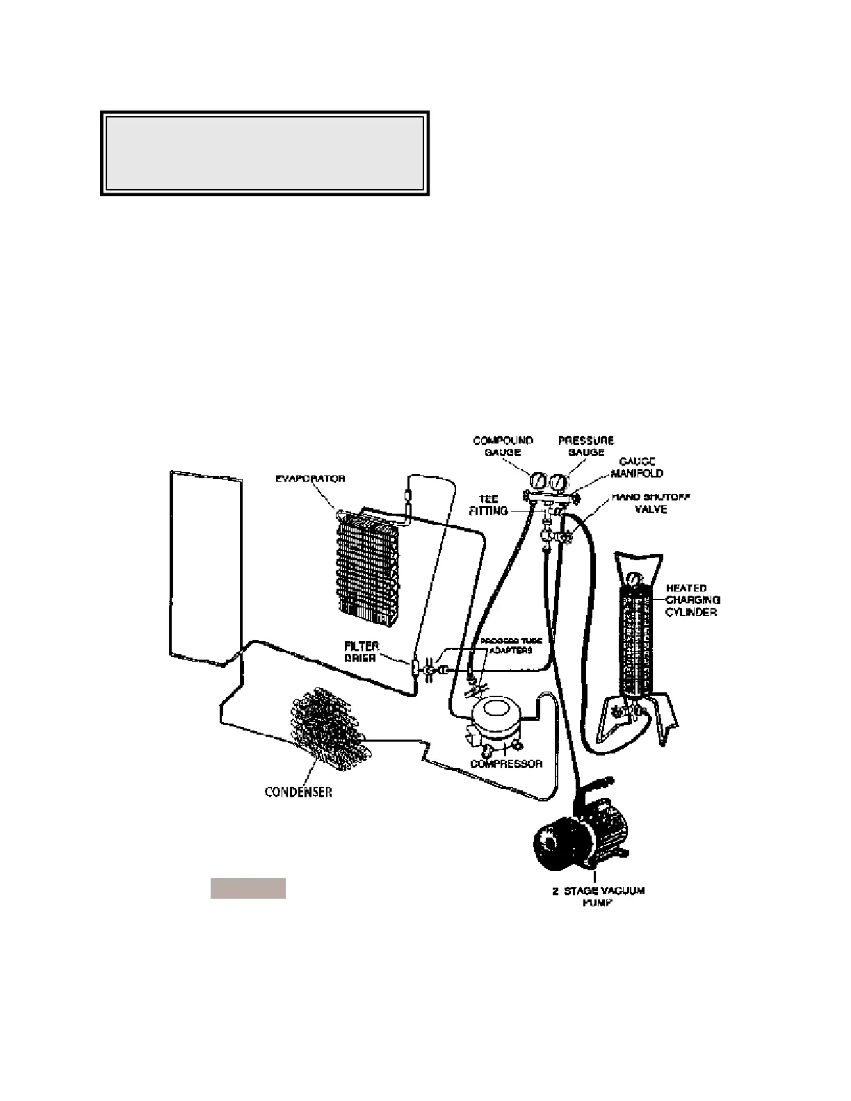
Figure E2