72
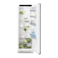
The control board is labeled: (See Figure 31.)
1. NEUTRAL One side of line to power board
2. CUBE Connected to solenoid for ice cubes
3. AUGER Connected to auger motor
4. FICE Fast Ice/Fast Freeze Feature
5. WATER Connect to water valve yellow coil
6. 120 VAC Other side of line to power the board
NEUTRAL
CUBE
AUGER
FICE
WATER
120 V AC
Figure 31
Connector on Control Board
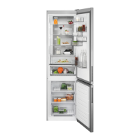
The relays on the board are numbered as follows: (See
Figure 32.)
K1 Controls the light in the dispenser
K2 Controls the water to the door
K3 Controls the solenoid for ice cubes
K4 Controls the auger motor
RELAYS K4, K3, K2, K1 Transformer
Figure 32
Diodes
Line voltage is supplied to the power board. A
transformer mounted on the board is used to reduce the
operating voltage. (See Figure 32.) There are four diodes
mounted on the board to convert the AC current to DC
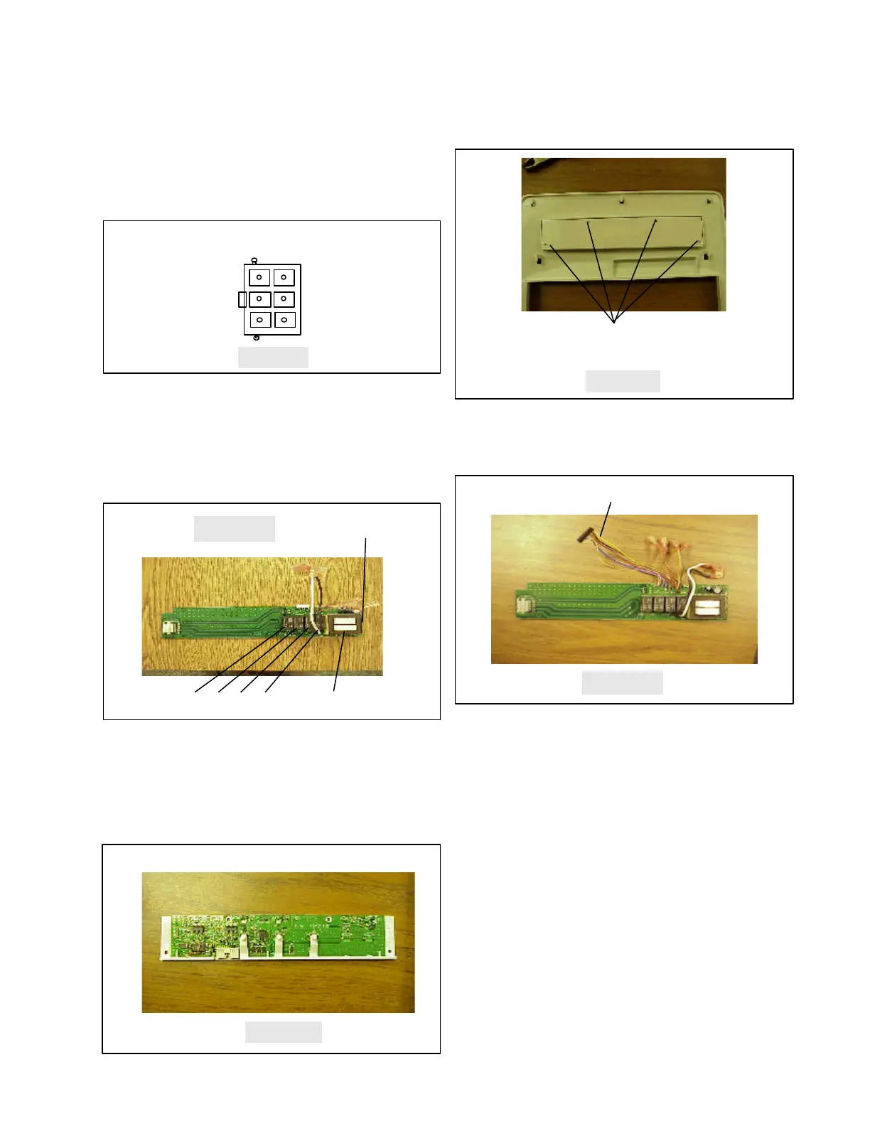
current. (Control Board - See Figure 33.) The operating
voltage for the control board is 8 to 13 VDC.
Control Board
Figure 33
The control board is mounted on the dispenser front
face. It can be serviced by removing the front face and
the four screws holding the cover over the board. (See
Figure 34.)
Figure 34
Remove 4 screws and lift up
the Control Board to replace
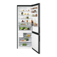
Current is carried between the power board and the
control board by a wire connector. (See Figure 35.)
Check the wires with an ohmmeter if you suspect a
broken wire.
Wire connector
Figure 35
The test points to check for voltage are located on the
face of the power board. (See Figure 36.)
To do the voltage test, remove the front cover but do
not disconnect the wire connector. Using a paper clip,
bend a loop around the end hook on the front face and
a hook in the other end of the wire. Place the second
hook in the center slot used for holding the front face.
(See Figure 37.) Use electrical tape around the wire to
prevent it from bridging some of the connection points
on the power board.
To test voltage, set your volt meter on DC 25 volts or
higher scale. With the front removed and hanging on
the wire, check for 8 to 12 VDC supply voltage to the
control board between the points called out in Figure
38. You will be able to make water and ice selections on
the control board. Press in the actuator arm and look
for your voltage drop to close the relay on the board
that operates the Auger, Water Valve, Solenoid, or light.
Power Board