36
© 2006, Elektro-Automatik GmbH & Co. KG
Irrtümer und Änderungen vorbehalten
EN
Instruction Manual
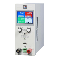
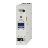
PS 8000 DT Series
Date: 02-09-2012
Parameter: BroadID Default: 0x7FF
Settings: 0x000...0x7FF(0...2047)
Meaning: Adjusts the broadcast ID (BCID) for the CAN ID sy-
stem with three IDs (Vector compatible, dbc les). This extra
ID is a fourth ID for the device which can be used for broadcast
messages to multiple units on a bus. Purpose if this ID is to
adjust it to the same value on all units that are targeted to be
controlled simultaneously by set values or device conditions.
Display can be switched from decimal to hexadecimal by
pushing any of the rotary knobs.
Only available, if IDSys = Vector has been selected. See
below at parameter IDSys.
Parameter: RID Default: 0
Settings: 0...31
Meaning: Selects the relocatable identier segment (RID). Refer
to CAN terminology or instruction manual of the IF-C1 CAN
interface card for further information.
Parameter: Busterm Default: yes
Settings: yes,no
Meaning: activates/deactives the bus termination resistor of
the CAN interface card. This is required if the device is at the
end of the bus.
Parameter: IDSys Default: Vector
Settings: Vector,normal
Meaning: Selects the CAN ID systems (IDSY). With „Normal“,
the former, old CAN ID system with two CAN IDs per unit is used,
where the IDs are built from „Devicenode“ (see above) and
„RID“ (see above) . Also see the external user manual for the in-
terface cards regarding the calculation scheme of the CAN IDs.
The other ID system, selected with „Vector“, uses three CAN
IDs per unit and it thus enables the use of so-called DBC les
to implement the device into Vector company software. By
selecting this ID system, two ID related settings (see above)
become active, where the user adjusts a base ID that denes
the three CAN IDs, plus a broadcast ID (if used).
Following settings only with RS232 interface IF-R1:
Parameter
:
Baud
Default
:
57600
Settings
:
9600,19200,38400,57600
Meaning: Selects the serial transmission baudrate (in baud).
Further parameters for the RS232 are not congurable, but
dened as follows:
Parity = odd
Stop bits = 1
Data bits = 8
and have to be set to the same co nguration at the PC.
Following settings only with Probus interface IF-PB1:
Parameter
: Profibus
Default
: 1
Settings
: 1-125
Meaning: Denes the Probus address of the device. This
address is used apart from the device node to implement and
access the unit on a eld bus system.
Operating the device
9. Digital interface cards
The device supports following pluggable interface cards:
IF-U1 (USB)
IF-R1 (RS232)
IF-C1 (CAN)
IF-G1 (GPIB/IEEE)
IF-E1 / IF-E1B (Ethernet/LAN + USB)
IF-PB1 (Probus + USB)
The cards require only a little or no setup after insertion. The
card specic settings are stored and kept, even if the card is
replaced by one of different type. Thereby it is not necessary to
congure the card settings everytime a card is inserted.
Details about the technical specs of the interface cards and the
handling, as well as instructions to implement the device into a
bus system or to control the device by means of a PC (LabView
etc.) can be found in the user manual for the IF cards.
Attention!
Insertion or removal only if the device is completely switched
off (power switch)!
About conguration of the interfaces see section „8. Device setup“.
The digital interface cards allow to set voltage, current and po-
wer, as well as the OVP threshold and undervoltage limit UVL
by means of a PC. When changing to remote control mode, the
device keeps the last set values until they‘re altered. Hence it
would be possible to control only voltage by sending arbitrary
set values and the current set value would remain unaltered.
Set values given by the digital interface (except GPIB) are al-
ways percentage and correspond at 100% (hex: 0x6400), resp.
at 110% (hex: 0x6E00) for the OVP threshold, to the nominal
values of the device. Using GPIB, any value is given as real
decimal value.
Furthermore, the digital interfaces allow to query and set a lot of
other features and values. For details refer to the user manual
of the interface cards.
 Loading...