39
Instruction Manual
PS 8000 DT Series
EN
Date: 02-09-2012
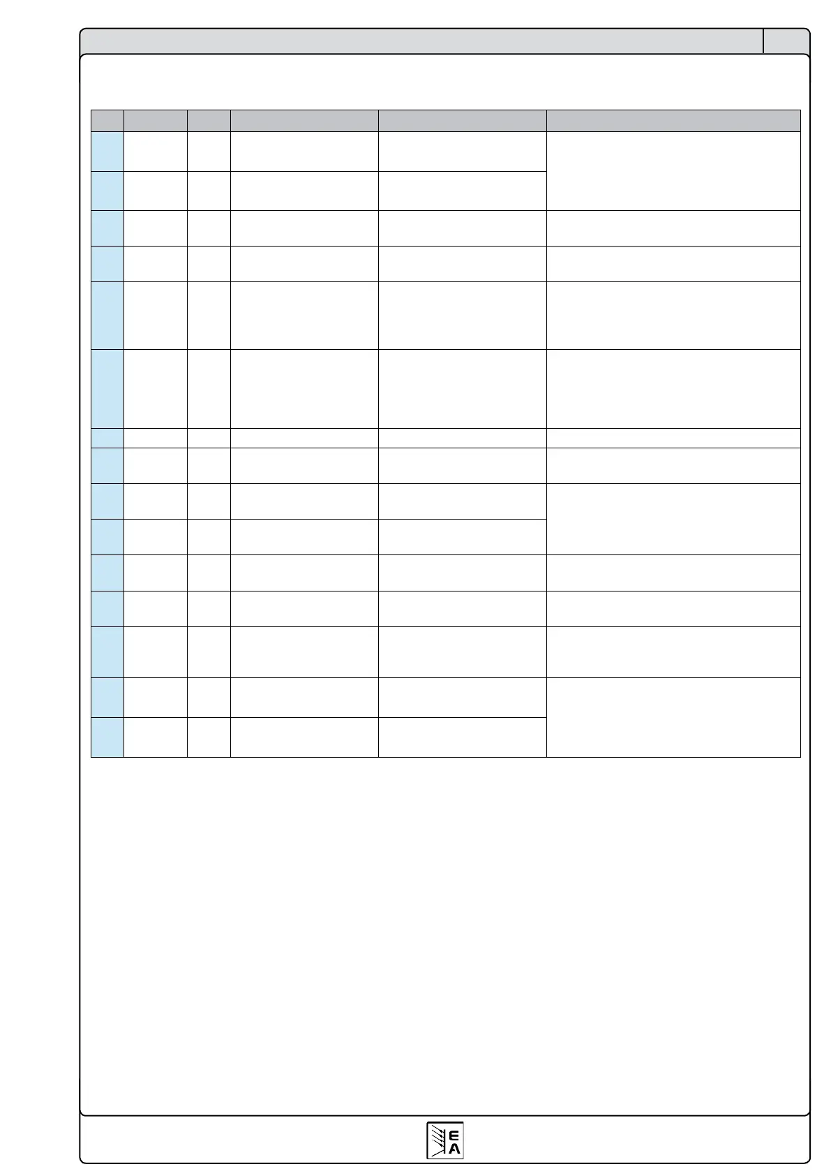
10.3 Pin specication
Pin Name Type
(1
Description Level Electrical specication
1 VSEL AI Set value: voltage
0…10V or 0...5V correspond
to 0..100% of U
Nom
Accuracy < 0,2%
Impedance R
i
>100k
2 CSEL AI Set value: current
0…10V or 0...5V correspond
to 0..100% of I
Nom
3 VREF AO Reference voltage 10V or 5V
Accuracy < 0.2% at I
Max
= +5mA
Short-circuit-proof against AGND
4 DGND POT
Reference potential for
digital control signals
For +Vcc, control and status signals
5 REMOTE DI
Toggle between internal
or external control
External = LOW, U
Low
<1V
Internal = HIGH, U
High
> 4V
Internal = open
U range = 0 …30V
I
Max
= +1mA at 5V
Sender: Open collector against DGND
6 OT/PF DO
Overtemperature error /
Power fail error
(4
Error = HIGH, U
High
> 4V
no error = LOW, U
Low
<1V
Quasi open collector with pull-up to Vcc
(2
At 5V at the output there will be max.+1mA
I
Max
= -10mA at U
CE
= 0.3V
U
Max
= 0...30V
Short-circuit-proof against DGND
7 N.C. Not connected
8 PSEL
(3
AI Set value: power
0…10V or 0...5V correspond
to 0..100% of P
Nom
Accuracy < 0.5%
Impedance R
i
>100k
9 VMON AO Actual value: voltage
0…10V or 0...5V correspond
to 0..100% of U
Nom
Accuracy < 0.2% at I
Max
= +2mA
Short-circuit-proof against AGND
10 CMON AO Actual voltage: current
0…10V or 0...5V correspond
to 0..100% of I
Nom
11 AGND POT
Reference potential for
analogue signals
For -SEL, -MON, VREF signals
12 +Vcc AO
Auxiliary voltage output
(Ref: DGND)
11...13V
I
Max
= 20mA
Short-circuit-proof against DGND
13 REM-SB DI Output off
off = LOW, U
Low
<1V
on = HIGH, U
High
> 4V
on = OPEN
U range = 0…30V
I
Max
= +1mA at 5V
Sender: Open-Collector against DGND
14 OVP DO Overvoltage error
OV = HIGH, U
High
> 4V
no OV = LOW, U
Low
<1V
Quasi open collector with pull-up to Vcc
(2
At 5V at the output there will be max.+1mA
I
Max
= -10mA at U
CE
= 0.3V
U
Max
= 0...30V
Short-circuit-proof against DGND
15 CV DO
Indication of voltage
regulation active
CV = LOW, U
Low
<1V
CC = HIGH, U
High
>4V
(1
AI = Analogue input, AO = Analogue output, DI = Digital input, DO = Digital output, POT = Potential
(2
Internal Vcc, approx. 14.3V
(3
Only with models from 1kW
(4
Power fail = input failure or PFC (reported only since rmware 6.01)
Operating the device
 Loading...