Revised March 30, 2005 Versa DRIVE C1
Page 4 of 11 DRAFT COPY User Manual
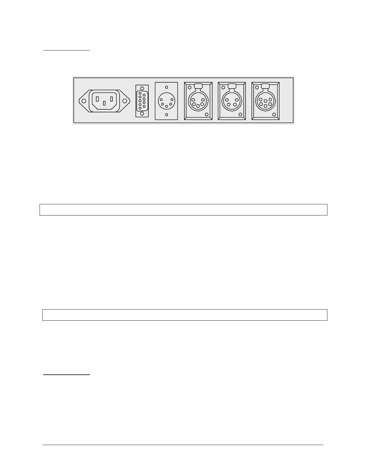
3.2 Rear Panel
AC Power Input
Contact
Closure
DMX
In
DMX
Out
Local Data
Output
Serial Data
Output
The Versa DRIVE C1 has the following connectors on its rear panel:
• IEC AC Power Input (85-264VAC, 50/60Hz)
• DB-9 Connector for Contact Closure Input
• DMX Input – 5 pin XLR
• DMX Output (thru) – 5 pin XLR
• Local Data Output – 4 pin XLR
• Serial Data Output – 6 pin XL
4. Setup
1. Connect the data output cable from the back of the C1 into the first Versa TUBE or TILE.
2. Connect AC Power from an outlet to the Versa DRIVE and Versa TILE /TUBEs.
3. Tubes are daisy-chained together using 2 and 4-pin JYC data cables.
Tile panels daisy-chained together using 6-pin JYC cables.
4. Insert Compact Flash card in the front of the Versa DRIVE
5. Power on Versa DRIVE and Versa TILE and/or Versa TUBEs.
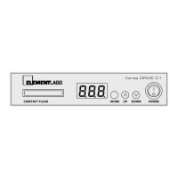
5. Versa DRIVE Menu System
The C1 can be controlled from the front panel with a simple menu system. A three digit numeric LED display
shows the current menu item and its value.
Navigation is accomplished with the three buttons:
5.1 Navigation
The C1 can be controlled from the front panel with a simple menu system. A three digit numeric LED display
shows the current menu item and its value.
Navigation is done with the three buttons:
MENU – Steps back one level in the menu system
UP – Scrolls up through available menu items or parameter values
DOWN – Scrolls down through available menu items or parameter values
 Loading...