Revised March 30, 2005 Versa DRIVE C1
Page 7 of 11 DRAFT COPY User Manual
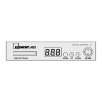
5.3.8 Firmware
This mode displays the current firmware version of the C1. The UP and DOWN buttons have no effect in this
mode.
5.3.9 Link and Lock
The Link mode sets the type of control the Versa DRIVE has over a system.
MSt (Master), SLA (Slave), and 0FF
(OFF) are the three options.
After short period of inactivity (about 10 seconds), the UP and DOWN buttons go into the Lock mode, and are
disabled. This prevents accidentally changing of parameter values. If the UP or DOWN buttons are pressed while
the C1 is in Lock mode, the display will show
LOC.
Pressing the MODE button immediately unlocks the C1. When the C1 is unlocked, it immediately goes into the
PATTERN mode:
PAt. In the Lock mode, the display will revert to showing the current pattern number after a
two second delay.
6. Contact Closure
A “dry-contact“ is simply a normally open, single-pole, single-throw (SPST) switch or pushbutton, such as the
output side of a relay, etc.
! WARNING: Severe risk of electric shock. No user-serviceable parts inside.
The contact closure can be used to trigger playback of the first 8 user-defined patterns in the C1. It is not
restricted specifically to patterns 1 – 8. If the lowest number pattern on the CF card is 17, then contact closure #1
would trigger pattern 17.
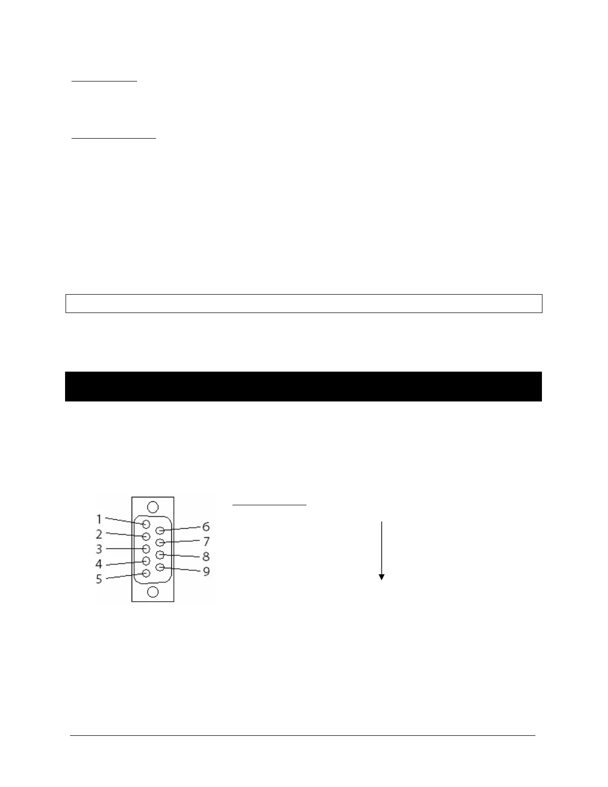
The contact closure connector is a standard, commonly available DB-9.
Pin # Function
1 Pattern A – the lowest numbered user-defined pattern
2 Pattern B
3 Pattern C
4 Pattern D
5 Pattern E
6 Pattern F
7 Pattern G
8 Pattern H – the 8th lowest user-defined pattern
9 Common (+5VDC)
The contact closures use 5VDC at 1mA per closure. A dry contact switch can be connected at a distance of up to
1,000 meters using 24 AWG wire.
Female DB-9
! WARNING: NEVER apply any external voltage or data to the DB9 connector.
 Loading...