-58-
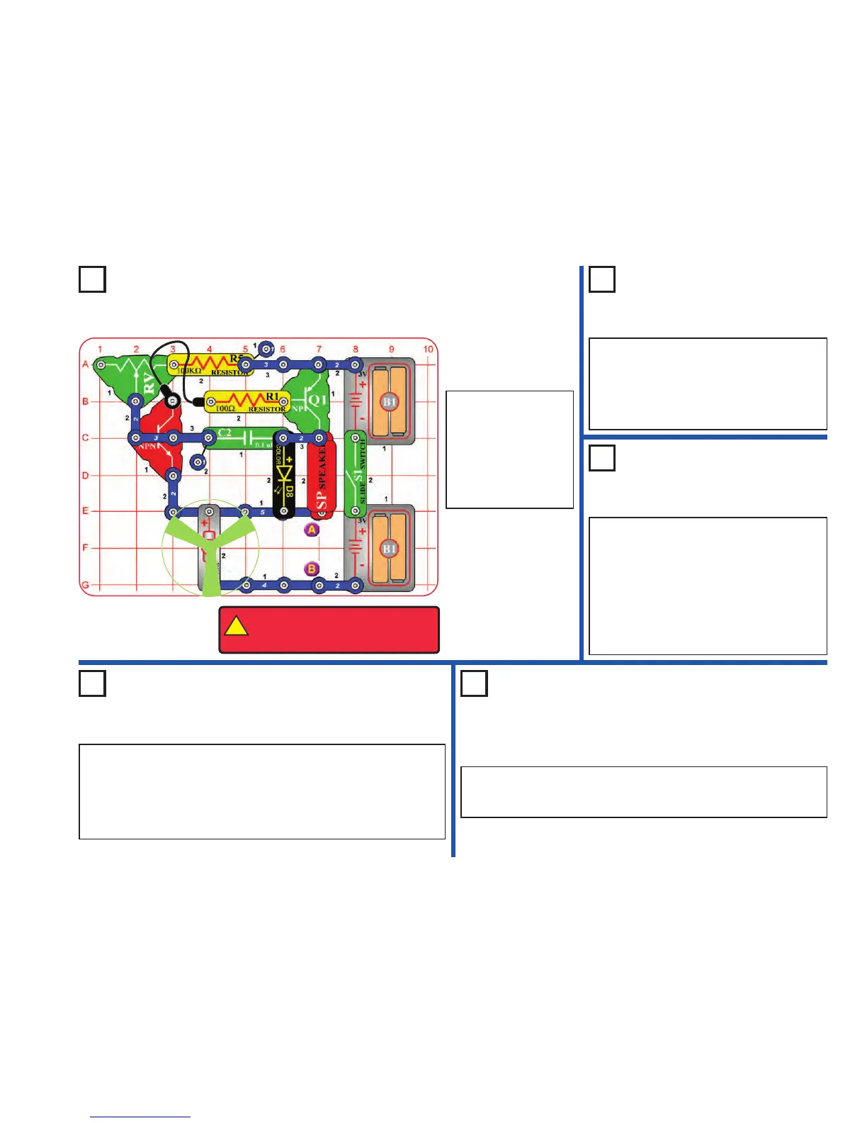
Project 121
High Power Buzzer
Project 123
Photo Buzzer
Use the circuits from projects 121-122, but add the
phototransistor (Q4) across base grid locations B2-
B4 (between RV and R1, “+” on the left), on level 3.
Shine a bright light on the phototransistor to change
the sound, while also moving the lever on RV.
You can also place the phototransistor directly
over the 100kΩ resistor, as done for the 5.1kΩ
resistor in project 122. For this arrangement,
“+” on Q4 should be on the right.
Project 124
Step Beeper
Use the circuits from projects 121-123, but replace the 0.1µF capacitor
(C2) with the 100µF capacitor (C4), “+” to the right. The motor will move
in small bursts, with long intervals or almost continuously, depending on
the resistors and phototransistor.
Next, replace the color LED (D8) with the white LED (D6). See how the
circuit works now.
Project 125
Wacky Buzzer
Repeat projects 121-123, but add the 100µF capacitor (C4) across the
points marked A & B in the drawing (“+” to A). The motor may not spin but
the sound is different. The sound may not be very loud.
Project 122
Buzz Fan
Use the preceding circuit, but place the 5.1kΩ
resistor (R3) directly over the 100kΩ resistor
(R5) using a 1-snap. The pitch of the tone is
higher now, and the fan spins. The circuit may
not make noise on all settings for the
adjustable resistor. The motor may not spin.
Build the circuit as
shown and turn on the
switch (S1). Move the
lever on the adjustable
resistor (RV) to vary the
pitch of the buzzing
sound. The motor (M1)
may not spin.
!
WARNING: Moving parts. Do not
touch the fan or motor during
operation.