-39-
Project #222
OBJECTIVE: To learn about the most important
Transistor Amplifiers
OBJECTIVE: To show how electronic amplifiers can OBJECTIVE: To show how electronic amplifiers can
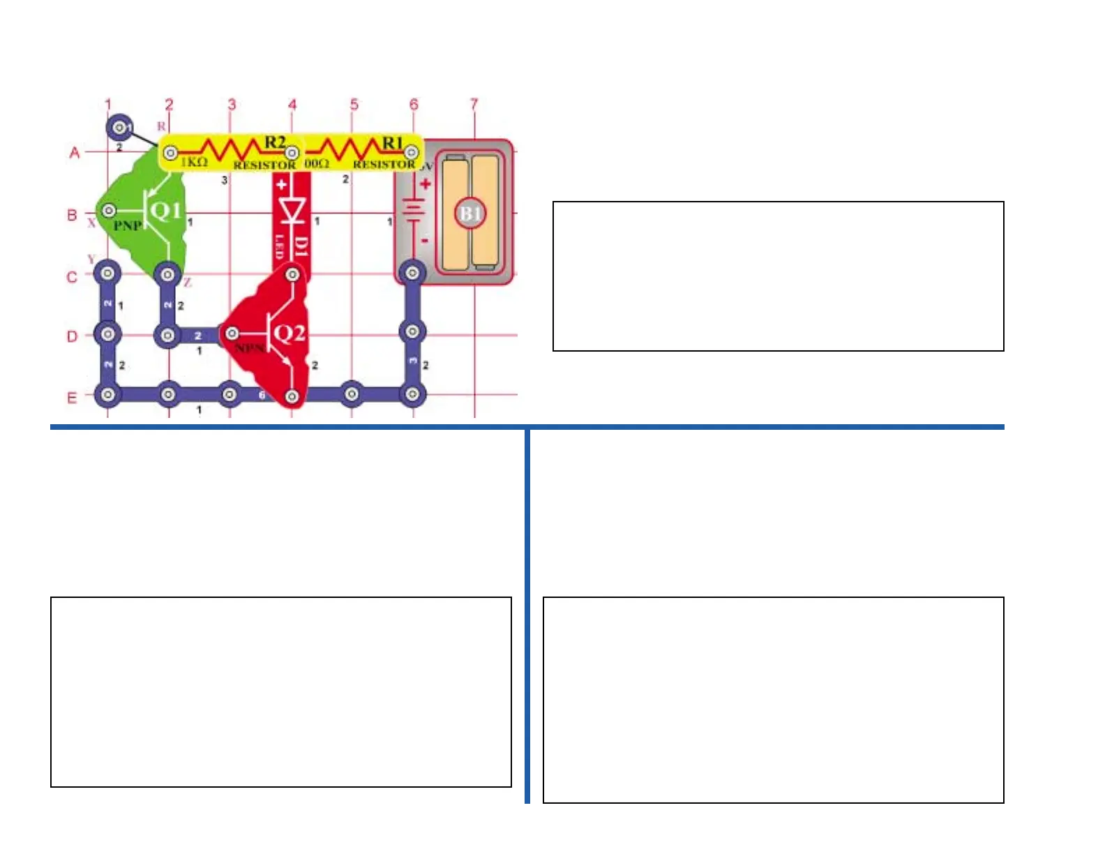
Use the circuit from Project 222 shown above.
When you placed your fingers across the two snaps marked X & Y you
noticed the LED came on in Project 222. Repeat this process, but this
time press very lightly on the two snaps marked X and Y. Notice how
the brightness of the LED is dependent on the amount of pressure you
use. Pressing hard makes the LED bright while pressing very gently
makes it dim or even flash. This is due to what technicians call contact
resistance. Even switches made to turn your lights on and off have
some resistance in them. When large currents flow this resistance, will
drop the voltage and produce the undesirable side effect of heat.
Project #223
Pressure Meter
Project #224
Resistance Meter
When you place one or more fingers across the two snaps marked X
& Y you will notice the light comes on. The two transistors are being
used to amplify the very tiny current going through your body to turn
on the LED. Transistors are actually electrical current amplifiers. The
PNP transistor has the arrow pointing into the transistor body. The
NPN transistor has the arrow pointing out of the transistor body. The
PNP amplifies the current from your fingers first, then the NPN
amplifies it more to turn on the LED.
Use the circuit from Project 222 shown above
When you placed your fingers across the two snaps marked X & Y you
noticed the LED came on in Project 222. In this project, you will place
different resistors across R and Z and see how bright the LED glows.
Do not snap them in; just press them up against the snaps labeled R
and Z in the diagram above.
First, place the 100kΩ resistor across the R & Z snaps and note the
brightness of the LED. Next, press the 5.1kΩ resistor across R & Z.
Notice how the LED gets brighter when the resistance is less. This is
because the NPN amplifier gets more current at its input when the
resistance is lower. The PNP amplifier is not used in this test.
 Loading...