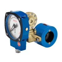
If you are installing the threaded versions, GL and GSS-versions, please
make sure that you are not using so called ”tube fittings”. We have often
seen them to have a much smaller inside diameter than the pipe section,
even though the size of the thread match. This can create a jet stream of the
fluid/gas, which will cause the differential pressure to be too low and you
will not get a good or accurate reading.
guideline only. The straight runs must befree from valves, bends or
in/decreasing diameters. Any of these disturbances must be placed before
and preferably after you start counting the straight runs.
The following inside diameters apply for the threaded Pipe Sections:
GL-and GSS 15 = 16 mm
GL-and GSS 20 = 21 mm
GL-and GSS 25 = 26 mm
GL-40 = 41 mm
Make sure that the Control unit, if mounted directly on the Pipe Section, is
placed on top of the Pipe Section and not under to prevent particles in the flu-
id to collect in the diaphragm housing. Please use a filter in the pipeline if you
suspect the fluid to contain particles.
The flanged models, FA and FSS-versions, must be aligned with the counter
flange and not placed in stress by tightening the bolts uneven. The flanged
models come with a gasket, and we recommend using this, as it is
dimensioned to suit the installation. Please see to that the gasket is properly
aligned and not disturbing the flow. It is also of outmost importance that the
connecting pipe and flange is of the same diameter (inside) and standard as the
pipe section. A mismatch can cause an erratic or incorrect reading of the flow.
If needed, please support the Flow Monitors with rigid brackets. There is no
problem in attaching the brackets directly to the Flow Monitor (see above),
but we recommend mounting them in the pipeline downstream and upstream
to avoid unnecessary stress in the installation area.
2.4
Separate mounting of the Pipe Section and
the Control Unit
Sometimes separate mounting of the Pipe Section and the Control Unit is re-
quested due to vibrations, high temperature or lack of space. As the Eletta
Flow Monitor is using the differential pressure caused by the orifice plate
mounted in the pipeline and directs these two pressures via two individual

 Loading...