EN
ENGLISH
3
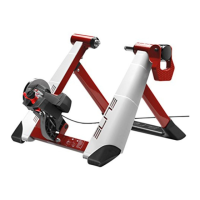
Thank you for choosing an Elite
hometrainer
Check the presence of all the following compo-
nents:
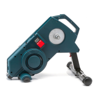
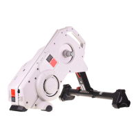
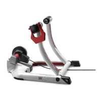
N°1 resistance unit
N°1 parts bag:
1 Allen wrench
2 M6 bolts
2 washers
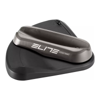
N°1 Command lever (Ref. A);
N°1 Belt (Ref. B);
N°1 Handlebar support (Ref. C);
N°1 Handlebar clamp support (Ref. D);
N°1 Screw (Ref. E);
N°1 Handlebar cover (Ref. F);
N°1 Anti-slip rubber (Ref. G)
INTRODUCTION
5IFSPMMFSJTUIFDZDMJTUTQBUIUPFGGFDUJWFUSBJOJOH
and improved performance.
For customized training, the resistance level can
be changed at any time with the command lever.
The simple and intuitive command lever features
8 sequential levels of resistance.
The command lever can be installed on all types
of bicycle handlebars and, with its two adapters,
can be installed on the either the handlebar or the
handlebar stem.
WARNING
t %P OPU CSBLF XIFO VTJOH UIF USBJOFS BT UIJT
can permanently damage roller and tyre
t5IFSFTJTUBODFVOJUIFBUTVQDPOTJEFSBCMZXIFO
in use
t5IFSFGPSFNBLFTVSFUPXBJUVOUJMJUDPPMTCFGPSF
touching the flywheel
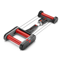
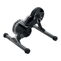
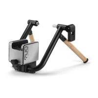
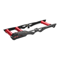
ASSEMBLING THE UNIT
t 3FTJTUBODFVOJUXJUINNEJBNFUFSSPMMFS
t 5PGJUUIFVOJU3FG"POUIFGSBNFGPMMPXUIF
instructions given in the Frame manual.
INSTALLING THE COMMAND LEVER
The command lever (Ref. A) can be installed on
either the handlebar or the handlebar stem.
t 0O UIF IBOEMFCBS NPVOU UIF IBOEMFCBS TVQ-
port (Ref. C) to the command lever (Ref. A) (Fig.
1) and connect it to the lever with the screw (Ref.
E) (Fig. 2 and 3).
!!WARNING!!
0OHandlebars with handlebar tape apply the
handlebar cover (Ref. F) to the handlebar support
(Ref. C) before installing the command lever (Ref.
A) on the handlebar (Fig. 4).
t4MJEFUIF TUSBQ3FG#UISPVHIJUT IPMFJOUIF
handlebar support (Ref. C) (Fig. 5 and 6).
0O handlebars without handlebar tape apply
the anti-slip rubber (Ref. G) to the strap (Ref. B)
(Fig. 7) by sliding the strap (Ref. B) through the
hole in the handlebar support (Ref. c) (Fig. 8) then
sliding the tip of the strap (Ref. B) through the
notch on the anti-slip rubber (Ref. G) (Fig. 9).
t .PVOU UIF DPNNBOE MFWFS UP UIF IBOEMFCBS
(Ref. A) then tighten it with the tightening handle
(Fig. 10 and 11).
t0OUIFIBOEMFCBSDMBNQBUUBDIUIFIBOEMFCBS
clamp support (Ref. D) to the command lever
(Ref. A) (Fig. 12) with the screw (Ref. E) (Fig. 13
and 14).
!!WARNING!!
When mounting to the handlebar stem, apply the
anti-slip rubber (Ref. G) to the strap (Ref. B) (Fig.
7); slide the strap (Ref. B) through the hole in the