MANUAL ACTIVATION OF THE
DEFROSTING CYCLE
To manually activate the defrosting cycle,
press the “UP” key for 5 seconds.
If defrosting conditions are not present,
(for example the evaporator probe
temperature is higher than defrost stop
temperature), the display
will blink three (3) times, in order to
indicate that the operation will not
be performed.
COPY CARD
The Copy Card is an accessory connected
to the TTL serial port which allows pro-
gramming quickly the instrument parame-
ters. The operation is performed as fol-
lows:
FrFormat
This command allows copy card formatting,
an operation recommended in case of first
use.
Warning: if the copy card has been pro-
grammed, using the “Fr” the data entered
are erased. This operation cannot be can-
celled.
UL-Upload
This operation loads the programming
parameters from the instrument.
dL-Download
This operation downloads to the instru-
ment the programming parameters.
NOTE:
• UPLOAD: instrument --> Copy Card
• DOWNLOAD: Copy Card --> instru-
ment.
The operations are performed accessing
the folder identified by the “FPr” label and
selecting, according to the case, “UL”, “dL”
or “Fr” commands; the operation is con-
firmed by pressing the “set” key. If the
operation is successful an “y” is displayed,
on the contrary, if it fails a “n” will be dis-
played.
TELEVIS SYSTEM
The link with the Televis system can go
through the serial port TTL (the BUS
ADAPTER 100 TTL RS-485 interface module
must be used).
In order to configure the instrument for
this purpose you must access the folder
identified by the “Add” label and use the
parameters “dEA” and “FAA”.
KEYBOARD LOCKING
The instrument includes a facility for dis-
abling the keyboard, by programming the
“Loc” parameter (see folder with “diS”
label). If the keyboard is locked, you can
still access the programming menu by
pressing the “set” key.
The Setpoint can also be viewed.
DIAGNOSTICS
The alarm condition is always signalled by
the buzzer (if present) and by the led of
the alarm icon
The alarm signal produced by a faulty
thermostat probe (referred to probe 1)
is shown as E1 on the instrument display
When the sensor detects an error condi-
tion:
• the code E1 is displayed
• the compressor is activated as indicated
by the "On" and "Off" parameters if pro-
grammed for the duty cycle or:
Other signalling alarm are not shown on
the instrument display, but from the
“Machine Status” menu within the “AL”
folder.
MINIMUM AND MAXIMUM TEMPERA-
TURE ALARMS
Regulation of the minimum and maximum
temperature alarms refers to the thermo-
stat probe.
The temperature limits defined by the
“HAL” (maximum temperature alarm) and
“LAL” parameters (minimum temperature
alarm) are in absolute temperature value.
When an alarm status occurs, if no alarm
exclusion phases are underway (see alarm
exclusion parameters), the alarm set icon
is lit up and the buzzer, and/or the relay
configured as an alarm, is activated. The
occurrence of this alarm does not in any-
way effect the control activities in
progress. This alarm status can be viewed
in the “AL” folder with AH1-AL1 labels.
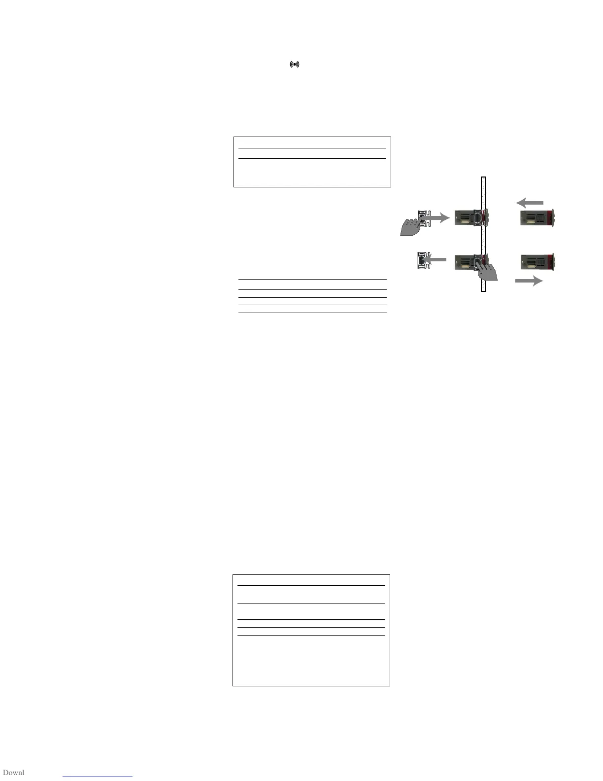
INSTALLATION
The instrument is designed for panel
mounting. Make a hole of 29x71 mm,
insert the instrument and fix it using the
brackets provided. Do not mount the
instrument in humid and/or dirty places; it
is suitable for use in ordinary polluted
places. Ventilate the place in proximity to
the instrument colling slits.
ELECTRICAL
WIRING
Attention! Never work on electrical
connections when the machine is
switched on.
The instrument is equipped with screw ter-
minal boards for connection of electrical
cables with a diameter of 2.5 mm
2
(one
conductor only per terminal for power
connections).
For the capacity of the terminals, see the
label on the instrument.
The relay contacts are voltage free. Do not
exceed the maximum current allowed; in
case of higher loads, use an appropriate
contactor. Make sure the power supply
voltage complies with the one required by
the instrument.
In 12V versions the power supply must be
provided by a security transformer with
the protection of a delayed 250 mA fuse.
Probes have no connection polarity and
can be extended using a regular bipolar
cable (note that the extension of the
probes affects the EMC electromagnetic
compatibility of the instrument: pay
extreme attention to wiring).
Probe cables, power supply cables and the
TTL serial cables should be distant from
power cables.
ID 961 LX/A 2/6
DISPLAY
E1
If simultaneous they will appear on display with 2
seconds alternation
ERROR
Thermostat probe fault
Probe Error table
Ont
0
0
>0
>0
Oft
0
>0
0
>0
Compressor output
OFF
OFF
ON
dc
DISPLAY
AH1
AL1
EA
oPd
To silence alarms press any key.
If silenced the LEDs will blink
Alarms are in absolute value or related to Setpoint
and (considered as the distance from the Setpoint
itself) depending on Att parameter.
ALARM
High temperature alarm (referred to
the thermostat probe or probe 1)
Low temperature alarm (referred to
the thermostat probe or probe 1)
Esternal alarm
Open door alarm
 Loading...