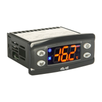
ID 961 LX/A 4/6
PAR.
diF
HSE
LSE
OSP
Cit
CAt
dOd
dAd
Ont
OFt
dOn
dOF
dbi
OdO
dit
dt1
dt2
dCt
dOH
dEt
dPO
tcd
Cod
Att
AFd
HAL
LAL
PAO
dAO
OAO
tdO
tAO
EAL
dEA
FAA
LOC
DESCRIPTION
COMPRESSOR REGULATOR (folder with “CP” label)
diFferential. Relay compressor tripping differential. The compressor stops on reaching the
Setpoint value (as indicated by the adjustment probe), and restarts at temperature value
equal to the Setpoint plus the value of the differential.
Note: the value 0 cannot be assumed.
Higher SEt. Maximum possible setpoint value.
Lower SEt. Minimum possible setpoint value.
Offset Setpoint: temperature value to be added algebraically to the setpoint in the case
of reduced set enabled (Economy function). It can be activated through digital input or
by a key configured for such use.Offset SetPoint
Compressor min on time. Minimum compressor activation time before any possible dis-
abling. If set at 0 it is not active
Compressor mAx on time. Maximum compressor activation time before any possible dis-
abling. If set at 0 it is not active
digital (input) Open door. Digital input user shut off. y = yes; n = no. Valid for parameter
“H11” = ±4 (door switch).
digital (input) Activation delay. Delay time of digital input activation.
COMPRESSOR PROTECTIVE DEVICE (folder with “CP” label)
On time (compressor). Compressor activation time in the event of faulty probe. If set to
“1” with Oft at “0” the compressor is always on, while at Oft >0 it functions always
in duty cycle mode.
OFF time (compressor). Compressor in disabled state time in the event of a faulty probe.
If set to “1” with Ont at “0” the compressor is always off, while at Ont >0
it functions always in duty cycle mode.
delay (at) On compressor. Delay time in activating the compressor relay after switch-on
of instrument
delay (after power) OFF. Delay after switch off; the indicated time must elapse between
switch-off of the compressor relay and the successive switch-on.
delay between power-on. Delay between switch-ons; the indicated time must elapse
between two successive switch-ons of the compressor.
delay Output (from power) On. Delay time in activating the outputs after switch-on of
the instrument or after a power failure.
DEFROSTING REGULATOR (folder with “dEF” label)
defrost interval time. Interval between the start of two successive defrosting operations.
U.M. Hours (default) /min/sec depending on dt1 parameter
defrost time 1. Measure unit for defrosting intervals (“dit” parameter).
0 = “dit” parameter in hours;
1 = “dit” parameter in minutes;
2 = “dit” parameter in seconds.
defrost time 2. Measure unit for defrosting duration (“dEt” parameter).
0 = “dEt” parameter in hours;
1 = “dEt” parameter in minutes;
2 = “dEt” parameter in seconds.
defrost Counting type. Selection of count mode for the defrosting interval.
0 = compressor operating hours (DIGIFROST® method);
1 = Real Time – appliance operating time;
2 = compressor stop.
defrost Offset Hour. Start-of-defrosting delay time from start up
of instrument.
defrost Endurance time. Defrosting time-out; determines duration of
defrosting. U.M. minutes (default) /hours/sec depending on dt2 parameter
defrost (at) Power On. Determines if at the start-up the instrument must enter defrosting
(if the temperature measured by the evaporator allows this operation).
y = yes, starts defrost at start-up; n = no, doesn’t start defrost.
time compressor for defrost. Minimum time for compressor On or OFF before defrost.
If >0 (positive value) the compressor will be ON for tcd minutes; If<0 (negative value)
the compressor will be OFF for tcd minutes. If =0 parameter is disregarded
Compressor off (before defrost). Time for compressor OFF in proximity of the defrost
cycle. If a defrost cycle is set within the programmed time for this parameter, the com-
pressor is not started up.
ALARMS (folder with “AL” label)
Alarm type. Parameter “HAL” and “LAL” modes, as temperature absolute values or as dif-
ferential compared to the Setpoint. 0 = absolute value; 1 = relative value.
Alarm Fan differential. Alarm differential.
Higher ALarm. Maximum temperature alarm. Temperature value (with regard to Setpoint)
which if exceeded in an upward direction triggers the activation of the alarm signal.
Lower ALarm. Minimum temperature alarm. Temperature value (with regard to Setpoint),
which if exceeded in a downward direction, triggers the activation of the alarm signal.
Power-on Alarm Override. Alarm exclusion time after instrument switch on,
after a power failure.
defrost Alarm Override. Alarm exclusion time after defrost.
Output (door) Alarm Override. Delay time for temperature alarm signalling after disabling
of digital input (or door closure).
Time-out Door Open. Alarm signalling delay time for gate open.
temperature Alarm Override. Temperature alarm signal delay time.
External Alarm Lock. External alarm for regulators stop. Allows the blocking of compres-
sor, defrosting and fan regulators if the digital input (configured as external alarm) is
activated. n = not block; y = block.
COMUNICATION (folder with label “Add”)
dEvice Address. Device address: indicates the appliance address to the management pro-
tocol
FAmily Address. Family address: indicates the appliance family to the management proto-
col
DISPLAY (folder with “diS” label)
Keyboard locking. However, you can enter parameter programming modify them along
with the status of this parameter in order to allow keyboard locking. y = yes; n = no
Tab. 1 Parameter Table
DEFAULT
2.0
99.0
-50.0
0
0
0
n
0
0
1
0
0
0
0
6h
0
1
1
0
30min
n
0
0
0
2.0
50.0
-50.0
0
0
0
0
0
n
0
0
n
RANGE
0.1...30.0
LSE..302
-55.0...HSE
-30.0...30.0
0...250
0...250
n/y
0…255
0...250
0...250
0...250
0...250
0...250
0...250
0...250
0/1/2
0/1/2
0/1/2
0...59
1...250
n/y
-31...31
0…60
0/1
1.0...50.0
LAL...150.0
-50.0...HAL
0...10
0..999
0…10
0…250
0...250
n/y
0...14
0...14
n/y
VALUE* LEVEL**
1
1
1
2
2
2
2
2
1
1
1
1
1
1
1
2
2
1
1
1
1
2
2
2
1
1
1
1
1
2
2
1
2
1
1
1
U.M.
°C/°F
°C/°F
°C/°F
°C/°F
min
min
flag
Min.
min
min
sec
min
min
min
hours
(/min/sec)
flag
flag
flag
min
min
(/h/sec)
flag
min
min
flag
°C/°F
°C/°F
°C/°F
hours
min
hours
min
min
flag
num
num
flag
**NOTE: At level 1 the folders will show only level 1 parameters. At level 2 the folders will show only level
2 parameters.
 Loading...