a) simple connection between base board
and keyboard*;
b) multiple connection between several
modules in the network (up to a max. of 5
modules)**
N.B.:
1) the modules can be base boards or
keyboards.
2) two adjacent modules must be less
than 10 m apart whereas the two fur-
thest modules must be less than 50 m
apart.
• “Link” serial (also called LONG DIS-
TANCE) through GND (optional for multi-
ple connection), + and - lines for:
a) simple connection between base board
and keyboard*;
b) multiple connection between several
modules in the network (up to a max. of
10 modules)**
NOTE:
1) the modules can be base boards or
keyboards;
2) *in this case an optional plug-in
module (vertical) is necessary for the
base board and an optional plug-in
module (90°) for the keyboard.
3)**in this case n optional vertical plug-
in modules and m optional plug-in
modules (90°) are necessary where:
n= no. of base boards; Caution! n≤5;
m= no. of keyboards. Caution! m≤5;
(See network example).
4) the distance between two modules
must be less than 10 m for a simple
connection whereas the distance
between two modules must be less
than 2000m for a network connection.
Digital outputs: 6 outputs on relays:
configurable:
•first output (A) 16 A SPST 1 Hp 250Va;
•second output (B) 16A SPDT 1 Hp 250Va;
• third output 8(3)A SPST 1/2 Hp 250Va;
•fourth output (D) 8(3)A SPDT 1/2 Hp
250Va;
• fifth output (E) 16 A SPST 1 Hp 250Va;
• sixth output (F) 8(3)A SPST 1/2 Hp
250Va;
Measurement range: from -55 a 140 °C.
Accuracy: better than 0.5% of bottom scale
+1 digit.
Resolution: 1 or 0.1 °C.
Consumption: 8 VA.
Power supply: 230 Va/c ±10% 50/60 Hz
Warning: check the power supply specified
on the instrument label; for information
on relay capacity and power supplies con-
tact the Sales Office).
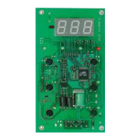
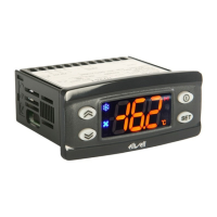
IWK KEYBOARD
TECHNICAL DATA
Front protection: IP65.
Casing: open board
Dimensions: 68.6 x 124.6mm, Max
h=6.5mm
Operating temperature: -5…55 °C.
Storage temperature: -30…85 °C.
Usage ambient humidity: 10…90 % RH
(non-condensing).
Storage ambient humidity: 10…90% RH
(non-condensing).
Display range: -50…110 (NTC); -50…140
(PTC) °C without decimal point (parameter
selectable), on display 3 digits + sign.
Measurement range: from -50 a 140 °C.
Accuracy: better than 0.5% of bottom scale
+1 digit.
Resolution: 1 or 0.1 °C.
Serials: see IWP Serial Output Table Power
Supply: from IWP power base module.
5/14
NOTE: The technical characteristics in this
document concerning measurements (range,
accuracy, resolution, etc.) refer to the
instrument in the strictest sense and not to
any accessories provided such as probes, for
example. This means, for example, that an
error introduced by the probe is added to
any error that is characteristic of the instru-
ment.
DIAGNOSTICS
DISPLAY
E1
E2
E3
If simultaneous, they will be shown on the display
alternately every 2 seconds
If E1 or E2 appears on the Master (see LINK net-
work) and the display is shared, the slaves will
always show the Master display: to understand
which unit is faulty, refer to the alarm LED for
each instrument.
FAULT
Faulty probe 1 (thermostat control)
Faulty probe 2 (evaporator) Faulty
probe 3 (display)
Table of faulty probes
DISPLAY
AH1
AL1
AH3
AL3
Ad2
EA
Opd
E7
E10
PA
LPA
HPA
Press any button to silence the alarm. The LED will
start to blink.
ALARM
High temperature alarm (referring to
room probe or probe 1)
Low temperature alarm (referring to
room probe or probe 1)
High temperature alarm (referring to
probe 3)
Low temperature alarm (referring to
probe 3)
Defrosting timed out
External alarm
Door Open Alarm
Master-Slave Communication failure
Clock battery alarm (se presente)
General pressure switch alarm
Minimum pressure switch alarm
Maximum pressure switch alarm
Alarm table
Type
TTL
Powered serial
(SHORT DISTANCE)
Optoisolated serial
(LONG DISTANCE)
Accessories
(on IWP base)
-
BUS ADAPTER 130
-
-
plug-in module
plug-in module
Use
Copy Card
Televis Connection Single
Base board-Keyboard con-
nection
Multiple Base board-
Keyboard connection
Single Base Board-
Keyboard connection
Multiple Base board-
Keyboard connection
IWP Serial Output Table (also see network connections)
Lines
TTL
TTL
GND, DATA, 12V
GND, DATA 12V
not connected
VDD, GND, +, -
VDD, +, - GND
optional
Type
Powered serial
(SHORT DISTANCE)
Optoisolated serial
(LONG DISTANCE)
Accessories
(on IWK keyboard)
plug-in module 90°
plug-in module 90°
Use
for Single Base-Keyboard
Connection
for Conn. Single Base-
Keyboard connection; for
multiple connections see below
IWK Serial Output Table (also see keyboard connections)
Lines
GND, DATA,
VDD
VDD, GND, +, -
IWP 760 LX Fan Condenser
 Loading...