7/14
NOTE: At level 1 the folders will only display all the level 1 parameters. At level 2 the folders will only display all the
level 2 parameters.
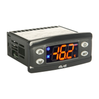
IWP 760 LX Fan Condenser
dS2 End of defrost temperature on 2nd evaporator
(determined by evaporator probe)
-50.0...150 -
2
- °C/°F
8.0
dE2 Defrost Time-out on 2nd evaporator; determines
maximum duration of defrosting on
2nd evaporator
1...250 -
2
- min
30
PAR. DESCRIPTION
RANGE DEFAULT
LEVEL** U.M.
dPO Determines when instrument starts up if the
defrosting cycle must be activated (if the tempera-
ture on the evaporator allows this)
y=defrosting activated at start-up
n=defrosting not activated at start-up
n/y n
1 flag
tcd Minimum time for each compressor state
before defrosting “Ontime if >0; “Offtime if >0
-31...31 0
2 min
Cod Compressor “Off” time before defrost cycle.
The compressor is not turned on if a defrost cycle
is expected in the time indicated by the parameter.
0=Function excluded
0...60 0
2 min
Fan controller-FAn label
Defrosting controller-deF label
FPt Determines if “FSt” and “Fot” are expressed as
absolute values or in relation to set point
0=absolute value; 1=value related to set point
0/1 0
2 flag
FSt Fan stop temperature. Temperature limit that, if
exceeded by the value read by the evaporator
probe, stops the fans.
-50.0...150.0 2.0
1 °C/°F
Fot Fan start temperature. If the temperature read by
the evaporator probe is lower than the set value
the fans remain off.
-50.0...150.0 -50.0
2 °C/°F
FAd Fan activation intervention differential.
(see “FSt”, “Fot”)
1.0...50.0 2.0
1 °C/°F
Fdt Delay before fan activation after defrosting
0...250 0
1 min
dt Dripping time
0...250 0
1
min
FCO Disables fans with compressor off (Off)
y = fans active (with thermostat; in response to
value read by defrost probe, see “FSt” parameter);
n = fans off;
dc = duty cycle (using parameters “Fon” and “FoF”
n/y/dc y
1 num
dFd Disables evaporator fans.
y=fans disabled
n=fans enabled
y/n y
1 flag
Fod Enables fan stop with door open and fan re-start
when door is closed (if fans were on).
n=fans stop;
y=fans unchanged
n/y n
2 flag
FdC Fan shut-down delay after compressor stop
0=function excluded
0...99 0
2 min
Fon Fan start-up time in Duty mode Cycle mode; valid
for FCO=dc and H42=1 (presence of probe 2)
0...99 0
2 min
FoF Fan shut-down time in Duty Cycle mode; valid for
FCO=dc and H42=1 (presence of probe 2)
0...99 0
2 min
Alarms-AL label
Att Determines if “LAL” and “HAL” are expressed as
absolute values or as a differential related to the
set point
0=absolute value 1=value related to set point
0/1 0
2 flag
Afd Alarm differential
1.0...50.0 2.0
1 °C/°F
HAL (4) Maximum alarm. Temperature limit (whose
absolute or relative value status is regulated by
“Att”) above which the alarm is activated.
LAL...150.0 50.0
1 °C/°F
LAL (4) Minimum alarm. Temperature limit (whose
absolute or relative value status is regulated by
“Att”) below which the alarm is activated.
-50.0...HAL -50.0
1 °C/°F
PAO (5) Alarm exclusion time after start-up of instrument
following a power failure
0...10 0
1 ore
dAO Alarm exclusion time after defrosting
0...999 0
1 min
“dd (2) dE1...dE8; daily defrost start time
0...23/0...59 24
1 ore/min
“Fd (2) F1...F8 festive defrost start time
0...23/0...59 24
1 ore/min
SCF Condenser fan set point
-50.0...150 0
1 °C/°F
dCF Condenser fan differential
-30.0...30.0 2
1 °C/°F
tCF Condenser fan start-up delay after defrost
0...59 0
1 min
dCd exclusion of condenser fans in defrost mode
n/y y
1 flag
n 1
0 2
0 2
0 2
6.0 1
-50.0 2
1 1
3 1
0
1
0 1
1 1
1 2
0 2
0 2
0 2
1 2
1 1
50.0 1
-50.0 1
3 1
60
1
- -
-
-
10 2
2 2
0 2
0 2
CUSTOM SETTINGS
DEFAULT - LEVEL
 Loading...