98764C (Rev. H - 06/16)
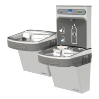
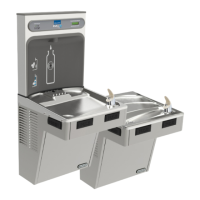
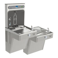
EZWSSM-1A, EZWSSMJO-2A, LZWSSM-1A, LZWSSMJO-2A
Page 4
Plumbing Connections
• Ensure lines and ports remain clean and free of contaminants during assembly.
• Purge each component if necessary.
• To ensure quick-connect connections seal properly, follow instructions per Figure 2.
Connect Electrical Power:
1. For 120V Models: Plug Power Cord into wall outlet.
1.1. For 220V Models: Thread one end of Power Cord Plug through Bottom Cover and into Power inlet of Bottle Filler,
then plug other end of power cord into wall outlet.
2. Conrmunitison:
2.1. Filtered Units: Both the Filter Status Green LED and the Bottle Counter LCD on the Nameplate are
illuminated.
2.2. Non-Filtered Units: The Bottle Counter LCD on the Nameplate is illuminated.
3. Ensure water dispenses: Activate unit by placing cup, hand or an opaque object in front of Sensor Lens and
watershouldow.Itisnormalforthewaterstreamtosputterwithairwhentheunitisneworanewltercartridge
is installed.
4. Ensureasteadywaterowisobtained:Activateunitperaboveandholduntilallairentrappedinlinesandlteris
purged. Since unit only dispenses water for 20 seconds per activation, multiple activations may be required.
5. Inspect for leaks and if any found, unplug unit and correct before continuing.
6. IfsettinguptheControlBoardforthersttime,gotoSetting the Control Board (below) before continuing.
7. For220VModels:PlaceCableClamp(supplied)onPowerCord(SeeFig.5)allowingsufcientslackforinstalling
and removing Bottom Cover with cord plugged in and secure Clamp with Screw (supplied).
8. Place Bottom Cover in position on underside of unit with long tab against wall and slide up into Back Panel
opening. Secure with two supplied Allen head screws using a 5/32" hex-wrench (not supplied).
9. For 120V Models: For a clean appearance, gather and loop any extra Power Cord and secure to the underside of
Bottom Cover with supplied adhesive backed clip.
Instruction for Use
1. Toactivatewaterow,positionmouthofwaterbottleorcontainerunderDispensingNozzleandinacontinuous
motion,swingandholdcontainerinfrontofSensorLens.Holduntilcontainerislledtoleveldesired.
2. Tostopwaterow,pullcontainerawayfromSensorLens.
1. Connect water supply line to unit:
1.1. Filtered Units: Connect the 3/8" O.D. poly tube (supplied factory attached on the Filter Head inlet
port) to the 3/8" Compression end of Service Stop Valve.
1.2. Non-ltered Units: Connect the 3/8"O.D. poly tube with Insulation to the 3/8" Compression end of
Service Stop Valve.
2. Connect water supply line from Filter:
2.1. Filtered Units: Connect the quick-connect Reducing Union Adapter Fitting, located at end of 3/8"O.D.
poly tube with Insulation, to the ¼” O.D. poly tube (supplied factory attached on the Filter Head outlet port).
2.2. Non-ltered Units: No connections necessary.
3. Connect the 1-1/4"O.D. Drain Tray Outlet to the in-wall Drain Line using a Slip Joint Drain Union or compression
clamp (not supplied). Tighten all connections water tight.
4. Install new Filter Cartridge by removing its protective cap, inserting into Filter Head and rotating Filter Cartridge
clockwise until it bottoms-out into Filter Head.
5. Turn water supply on, inspect for leaks and correct any leaks before continuing.
Connect Plumbing Lines
Changing the Filter
1. Remove the Bottom Cover of the Bottle Filler by removing the two (2) screws.
2. Removelterfromheadbyrotatingltercounterclockwise.
3. Removenewlterfromcarton,removeprotectivecap;capmaybeplacedonanoldltertoreducethe
chanceofthewaterspillingfromlterhousing.
4. Attachltertolterheadbyrmlyinsertingintoheadandrotatinglterclockwise.
5. ActivatesensoronBottleFilleruntilapproximately1gallonofwaterisdispensed.Thisushingprocedurepurges
airandnecarbonparticlesfromthelter.
BottleFillingStations.com