6
EL20
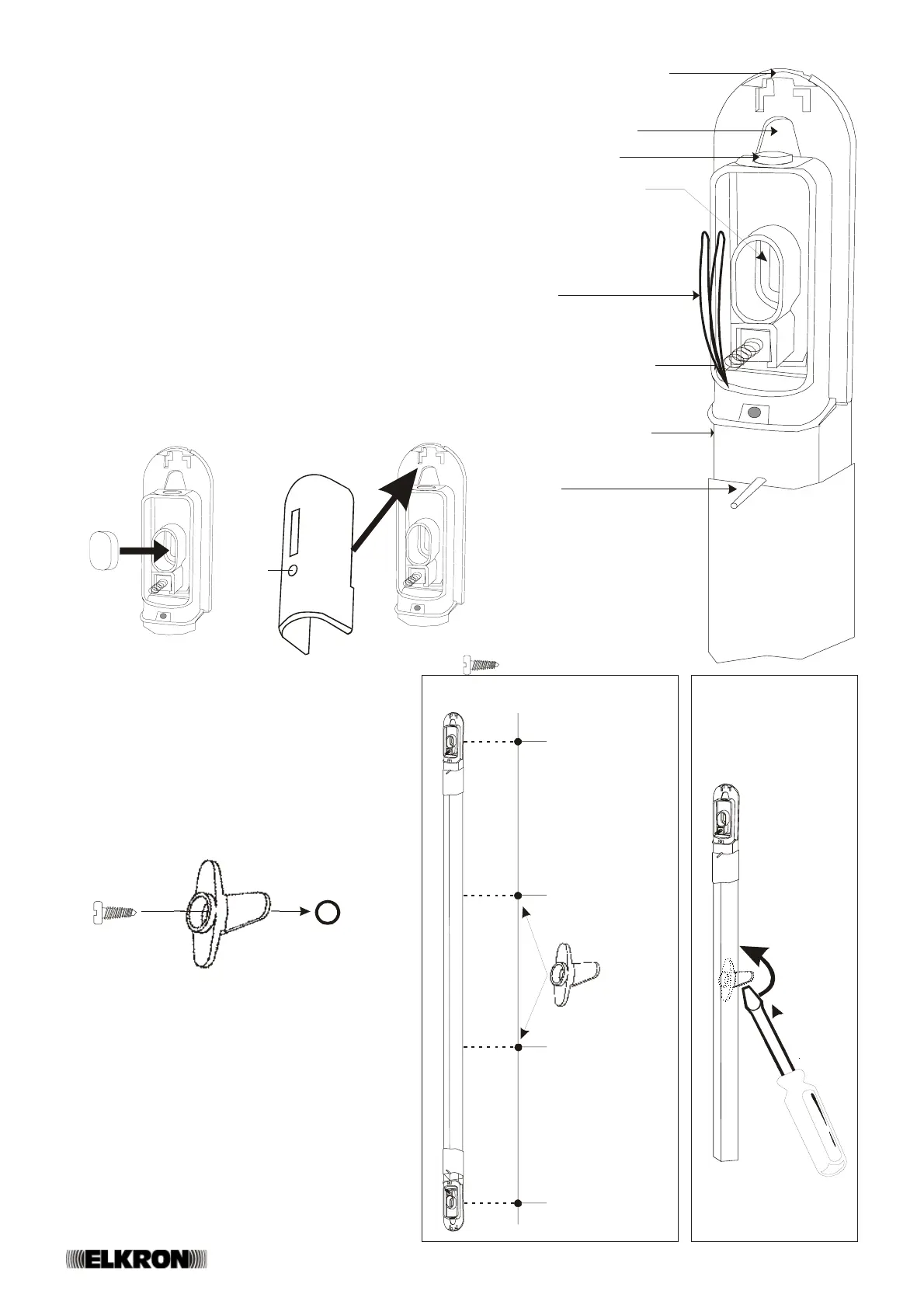
Installation
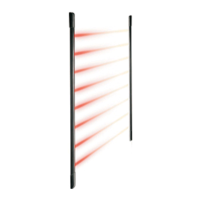
• Arrange the columns (receiver and transmitter) one opposite the
other at the same height (the optical power of the Tx column can
be programmed according to the distance between the two columns
- see TX Programming). Mark the fixing screw holes and drill the
supporting surface; intermediate blocks (supplied on production
models more than half a meter high) are available to improve the
column’s adhesion to the wall: Read the NOTE below if you wish to
use these blocks, otherwise go to the next step.
• Fix the column to wall by inserting the fixing screws inside the
appropriate slotted holes, and tighten them (Figure 6).
• Insert the oval-shaped rubber seal (supplied on production models)
as shown in Figure 4.
• Run the cable through the appropriate slotted holes (Figure 6) if
you wish to use the rear core hitch.
• If necessary, cut the programming jumpers (see par. “TX and RX
Programming”).
• Cut the column-stop posts (on the RX and TX) being careful to remove
any residual traces of burrs to avoid compromising the heat expansion
compensation (Figure 6).
• Close the cover and fasten with appropriate screw (see Figure 5).
Slotted hole for
rear core hitch
superior
core hitch
Slotted hole for wall
fixing screw
Programming
jumpers
Anti-removal/anti-
opening microswitch
Column-stop posts
Fig.4 Fig.5
RX
foro per vite
di fissaggio
foro per vite
di fissaggio
foro per blocco
intermedio
foro per blocco
intermedio
Fig.8
Fig.6
Core hitch
Rubber
seal
NOTE 1: COLUMN WALL FIXING
• After having marked the position of fixing screw holes,
drill the holes necessary for the intermediate blocks
(Figure 8).
• Fix the intermediate blocks (with appropriate screws)
making sure that blocking fins can rotate freely (see
Figure 7).
• Fasten the column to the wall using the screws
supplied for this purpose.
• Push the fins of the intermediate blocks with a
screwdriver so that they rotate (Figure 9).
Fig.9
INTERMEDIATE
BLOCK FIN
fig.7
support
Hole for
fixing screw
Hole for
fixing screw
Hole for
intermediate block
Hole for
intermediate block
 Loading...