8
EL20
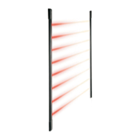
First powering up
• At first powering up, after the columns have been fixed one in front of the other, the beams are automatically synchronized by
the optical signal.
• The Coding of TX coupling with RX is performed automatically
• The receiver Led indicates any malfunctions:
- Led OFF: relay closed, barriers are functioning correctly
- Quick-flashing Led: see section titled “Troubleshooting”
Technical Characteristics
• RX-TX power supply nominal voltage ........................... 12 V—
• RX-TX power supply min-max ....................................... 10,5 - 15 V—
• Absorptions (typical-max) transmitter with 12 V— MIN RANGE MAX RANGE
EL20/05T........................................................................ 11 mA typ - 16 mA max 38 mA typ - 47 mA max
EL20/10T........................................................................ 13 mA typ - 20 mA max 64 mA typ - 73 mA max
EL20/15T........................................................................ 15 mA typ - 24 mA max 90 mA typ - 99 mA max
EL20/20T........................................................................ 17 mA typ - 28 mA max 116 mA typ - 127 mA max
• Absorptions (typical-max) receiver with 12 V— AT REST WITH ALARM
EL20/05R ....................................................................... 16 mA typ - 20 mA max 14 mA typ - 18 mA max
EL20/10R ....................................................................... 22 mA typ - 26 mA max 20 mA typ - 24 mA max
EL20/15R ....................................................................... 28 mA typ - 32 mA max 26 mA typ - 30 mA max
EL20/20R ....................................................................... 34 mA typ - 38 mA max 32 mA typ - 36 mA max
• Max range (adjustable on two levels) ............................ 10 m (Outdoor inst.) 20 m (Indoor inst.)
• Alarm times .................................................................... >0.1 sec (one ray interrupted)
1 sec (two adjacent rays interrupted)
• Emitters wave lenght...................................................... 940nm
• Issued signal .................................................................. PM transmission (pulse mode)
• Operating temperature certified (rules CEI) .................. -25°C - +55°C
• Alarm relay contact ........................................................ 0,1 A@24V— with serial protection R=10 Ohm
• Anti-tampering/anti-removal microswitch ..................... 50 mA@12 V—
• Degree of protection declared by builder....................... IP65 IK04
• Degree of protection certified (rules CEI) ...................... IP34
• Fault indication ............................................................... Red LED flashing
• Size and weight
EL20/05 .......................................................................... 500 x 25 x 23 mm - weight 250 g
EL20/10 .......................................................................... 1000 x 25 x 23 mm - weight 500 g
EL20/15 .......................................................................... 1500 x 25 x 23 mm - weight 750 g
EL20/20.......................................................................... 2000 x 25 x 23 mm - weight 1000 g
Trouble
Led is lit with fixed light
and the relay contact is
open.
Led is flashing and the
relay contact is open
Led is always OFF and
the relay contact is open.
Led is lit with fixed light
and the relay contact is
closed
Led is always OFF and
the relay contact is closed.
Possible Cause
• Incomplete acquisition of random code
• Power supply to TX column missing
• Barrier is excessively off-center
• Range selection jumper is not set correctly
• RX column fault
• Power supply to RX column missing
• Alarm memory enabled
• TC present
Corrective Measure
• Check that there are no obstacles
between barriers
• Supply TX column
• Re-position barriers
• Check the distance between barriers and
select the correct range
• Check the RX column and replace, if
necessary
• Supply RX column
• Arm the system and disarm, if necessary
(refer to the TC input)
• Arm the system and check connections
Troubleshooting
ELKRON S.p.A.
Via Carducci, 3 - 10092 BEINASCO (TO) - ITALY
TEL. +39.011.3986711 - FAX +39.011.3499434
www.elkron.it e-mail info@elkron.it
 Loading...