28 Installazione-Uso / Installation-User manual FL-FLR100
ERROR CODES
If an error condition occurs while the device operates, the En information is displayed, where n is an error
code reported in the table below:
Error code Meaning Recoverable
1 Autocalibration error due to too high or too low signal level YES
2 Autocalibration error due to unstable signal YES
3 Saturation error: the signal cannot be further compensated YES
4 Transmission error on the IIC peripheral NO
5 Dataflash initialization error NO
6 Dataflash block deletion error NO
7 Dataflash word read error NO
8 Dataflash word write error NO
9 Transmission error of a response frame to an UART1 command NO
When an error condition occurs, other than displaying the error code, the device also performs the following
operations:
• The fault relay switches;
• The yellow LED is turned ON;
• The program blocks itself.
Errors 1 and 2 are typical of the autocalibration procedure.
Error 3 is an internal error which occurs if the device cannot compensate a signal with a too high level.
The remaining errors are due to broken peripherals internal to the microcontroller mounted on the board.
The recoverable errors can be cancelled by moving the dip-switch DS8 to the ON position, in order to
restart the alignment procedure.
The unrecoverable errors, conversely, block the program indefinitely
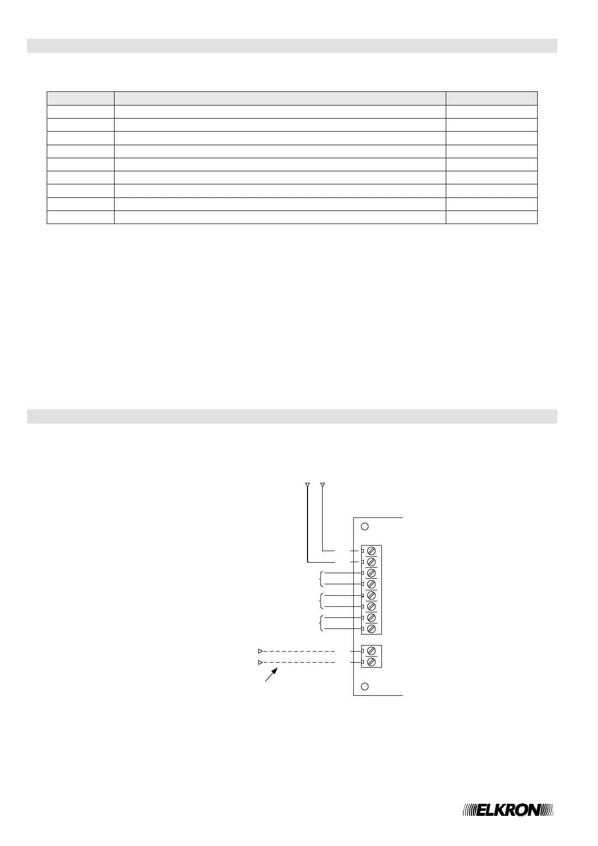
CONNECTIONS
Figure 8 - Example of connections of the Tx, Rx or Tx/Rx unit
M2
M1
(+)
(-)
(+)(-)
Power Supply
24 Vdc
(+)
(-)
Conventional detection
circuit from a fire
detection control panel
(+)
(-)
Optional, only use on
Rx or Tx/Rx units
Tx, Rx or Tx/Rx unit
Fault relay contact
Pre-alarm relay contact
Alarm relay contact