6
Presser foot
Needle plate
Screw(A)
Presser foot
lifter
Presser bar
Top of the needle plate
Bottom of the
presser foot
4mm
Presser
foot
PRESSER FOOT HEIGHT
4 mm (C)
Presser foot line
10 mm
Thumb screw
Bottom of the
needle bar (B)
2 mm
6 mm
8 mm
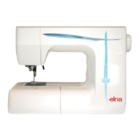
MECHANICAL ADJUSTMENT
PRESSER BAR HEIGHT AND ALIGNMENT
TO CHECK:
1. Lower the presser foot lifter.
2. The distance between bottom of presser foot and top of needle plate should be 4.0 mm (0.16") when the
presser foot is set at the standard position (The second line from the top aligns with the bottom of the
presser bar.)
ADJUSTMENT PROCEDURE:
1. Remove the face cover (see page 1).
Remove the lamp from the lamp socket, then lower the presser foot lifter.
2. Loosen the thumb screw. align the bottom of presser bar (B) and the second line (C) from the top on the
presser foot.
3. Adjust the distance between bottom of presser foot and top of needle plate to 4.0 mm.
4. Adjust the direction of the presser bar so the presser foot is parallel to the neelde plate. tighten the screw.
5. Attach lamp and face cover.
Thumb screw