SAFETY
DISCONNECTFROMTHEMAINSELECTRICAL
SUPPLYBEFOREREMOVINGANYCOVERS.
Never attempt to replace the immersion heater(s)
other than with the recommended immersion
heater(s).
DO NOT BYPASSTHETHERMALCUT-OUT(S)
INANYCIRCUMSTANCES.Ensurethetwo
malespadeterminationsontheundersideofthe
combinedthermostatandthermalcut-outare
pushedrmlyontothecorrespondingterminations
ontheelementplateassembly.
Incaseofdifcultycontactservicesupport;contact
detailsavailableatthebackofthisbooklet.
ELECTRICALSUPPLY
Allelectricalwiringshouldbecarriedoutbya
competentelectricianandbeinaccordancewiththe
latestI.E.EWiringRegulations.
Each circuit must be protected by a suitable fuse
and double pole isolating switch with a contact
separation of at least 3mm in both poles.
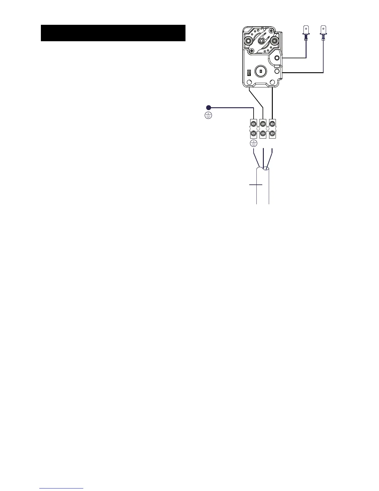
Theimmersionheater(s)shouldbewiredin
accordancewithFig7.Theimmersionheaters
MUSTbeearthed.Thesupplycableshouldbe
1.5mm
2
3coreHOFRsheathedandmustberouted
throughthecablegripprovidedwiththeoutersheath
ofthecablermlysecuredbytighteningthescrews
onthecablegrip.
DO NOT operate the immersion heaters until the
cylinder has been lled with water.
Ensurethethermostatandthermalcut-outsensing
bulbsarepushedfullyintothepocketsonthe
elementplateassembly.
PLUMBINGCONNECTIONS
Directcylindersrequirethefollowingpipework
connections.
Coldwatersupplytoandfrominletcontrols.•
Outlettohotwaterdrawoffpoints.•
Dischargepipeworkfromvalveoutletsto•
tundish.
INSTALLATION - DIRECT
Fig.7:Electricalconnections(directschematic)