4
Coral E
4. INSTALLATION
4.1.Position the unit and make the water connections
Refer to Fig. 2 for the recommended route of the pipework to the unit.
1. You will find a lid in the feed and expansion tank.
2. Place the unit in position. Ensure that the face of the unit with the immersion heaters is to the front.
3. Connect the mains cold water supply to the unit. See Fig. 2. Ensure that an isolating valve and a Y type line
strainer are fitted just before the unit.
In hard water areas it is recommended that a scale reducer is fitted in the mains cold water supply to the unit.
4. Connect a suitable overflow system to the overflow fitting. See Fig. 2. Copper tubing is recommended.
5. Connect the domestic hot water draw-off pipework to the blending valve.
6. Fit a drain cock to the ½" BSP boss on the front of the unit.
Notes:
i. For optimum performance we recommend a dedicated 22 mm mains cold water supply to the unit and a 15
mm hot water outlet. If the mains cold water supply pressure is less than 1 bar we recommend a 22 mm hot
water outlet.
ii. The mains cold water supply should be flushed before connecting it to the unit.
iii. Adequate clearance must be allowed for the pipe runs to the unit. From an appearance point of view and for
reduced heat loss from pipework we recommend that the pipework is run up the rear of the unit if possible.
iv. The overflow connection may be taken from the right hand or the rear of the unit. Copper tube recommended.
4.2.Electrical connection
Refer to wiring diagrams in section 8.
All electrical wiring must be carried out by a qualified electrician, and must be in accordance with BS 7671 -
Regulations for Electrical Installations, IEE Wiring Regulations and any local regulations which apply.
The mains supply required is 230/240 V ~ 50 Hz (each heater fused at 13 A).
Ensure the electricity supply has been isolated.
The immersion heaters must be connected using 85°C heat resistant rubber insulated HOFR sheathed flexible
cord 1.5 mm².
A double pole isolating switch with a contact separation of at least 3 mm in each pole must be incorporated in each supply.
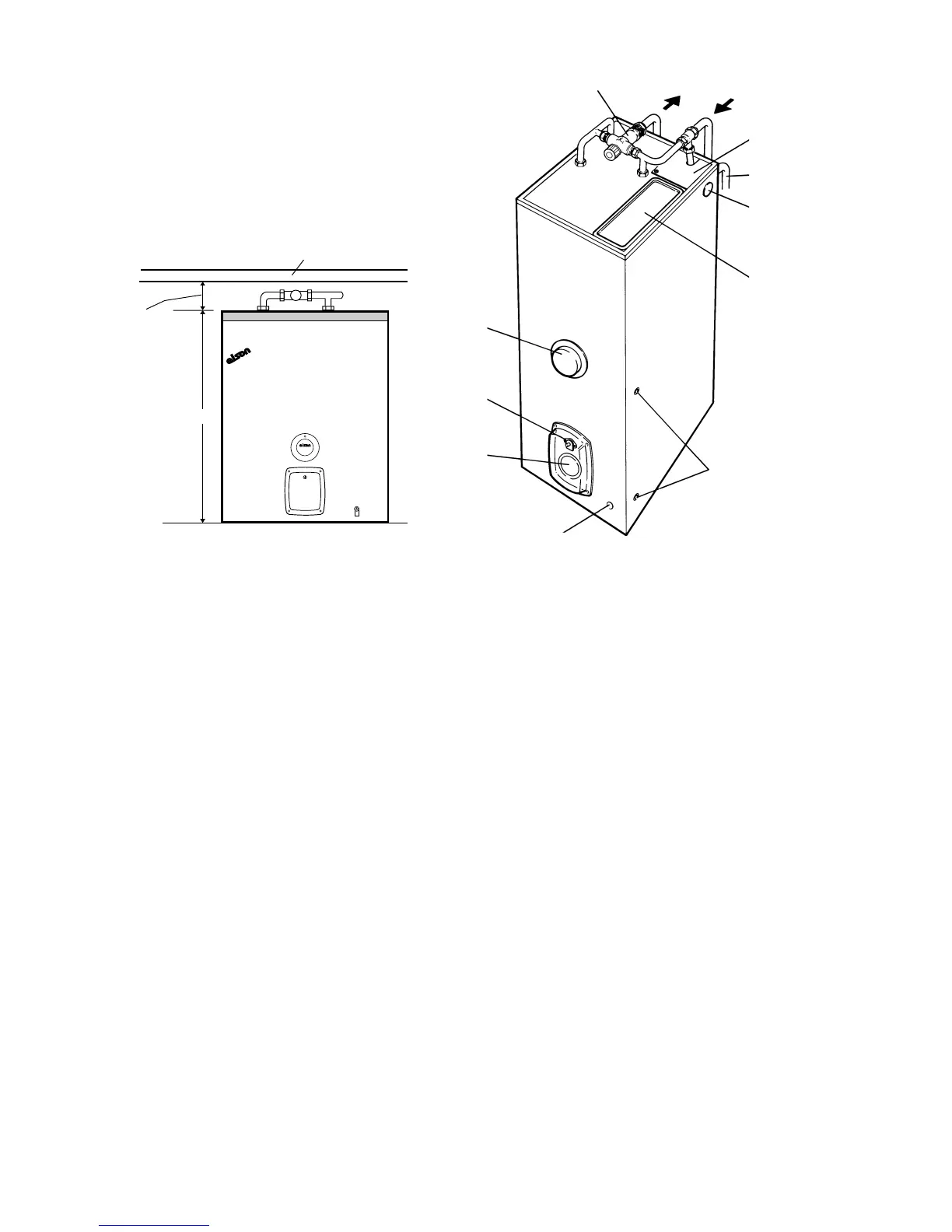
3.2.Clearances
A minimum 10 mm is required at each side (additional access
for the wiring is required at the right hand side, see Fig. 2).
225 mm is required above the unit for ball valve replacement.
Full frontal access must be available for installation and
removal/replacement of components.
Allow a minimum of 100 mm on the depth to accommodate
the immersion heater covers and plumbing connections.
Adequate clearance must be allowed for water and overflow
connections. Refer to section 4.1 for further details.
750
100 mm
clearance for
blending valve
Removable work surface
CORAL E
Fig. 1 - Coral E 100 UWS
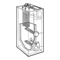
Fig. 2
Side entry
points for wiring
(RH side only)
Alternative
overflow
connection
Feed and
expansion
tank
Overflow
Overflow
connection
access plate
Mains cold
water *
Hot
water *
Blending valve
* Hot and cold
pipework may
also be run to the
unit from above
or left/right hand
sides.
'Boost'
immersion
heater
User
accessible
overheat limit
thermostat
'Overnight'
immersion
heater
Drain boss