Indicator of failover modes operation.
Backup power source indicator.
Functional key that reboots the device and resets it to factory settings:
Pressing the key for less than 10 seconds reboots the
device;
Pressing the key for more than 10 seconds resets the
terminal to factory settings.
Console port RS-232 for local management of the device.
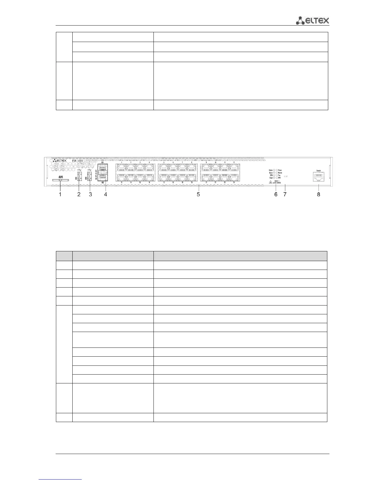
ESR-1000 front panel
The front panel of ESR-1000 is represented in Figure 2.2
Figure 2.2– Front panel of ESR-1000
The list of connectors, light indicators and controls that are located on the front panel of ESR-1000
are described in Table 2.2
Table 2.2 – Description of connectors, light indicators and controls located on the front panel of ESR-1000
10G SFP+/ 1G SFP transceiver installation slots.
24 Gigabit Ethernet 10/100/1000 Base-T (RJ-45) ports.
Indicator of device's current state
Existence and emergency level indicator of the device.
Existence indicator of active VPN-sessions
Activity indicator of exchange with data storages (SD-card or USB
Flash).
Operation indicator in failover-modes.
Emergency indicator of fans.
Reserve power supply indicator.
Functional key that reboots the device and resets it to factory settings:
– Pressing the key for less than 10 seconds reboots the device;
– Pressing the key for more than 10 seconds resets the terminal
to factory settings.
RS-232 console port for local device control.

 Loading...
