6 ESR series routers
ESR-1000, ESR-1200
1
back panel
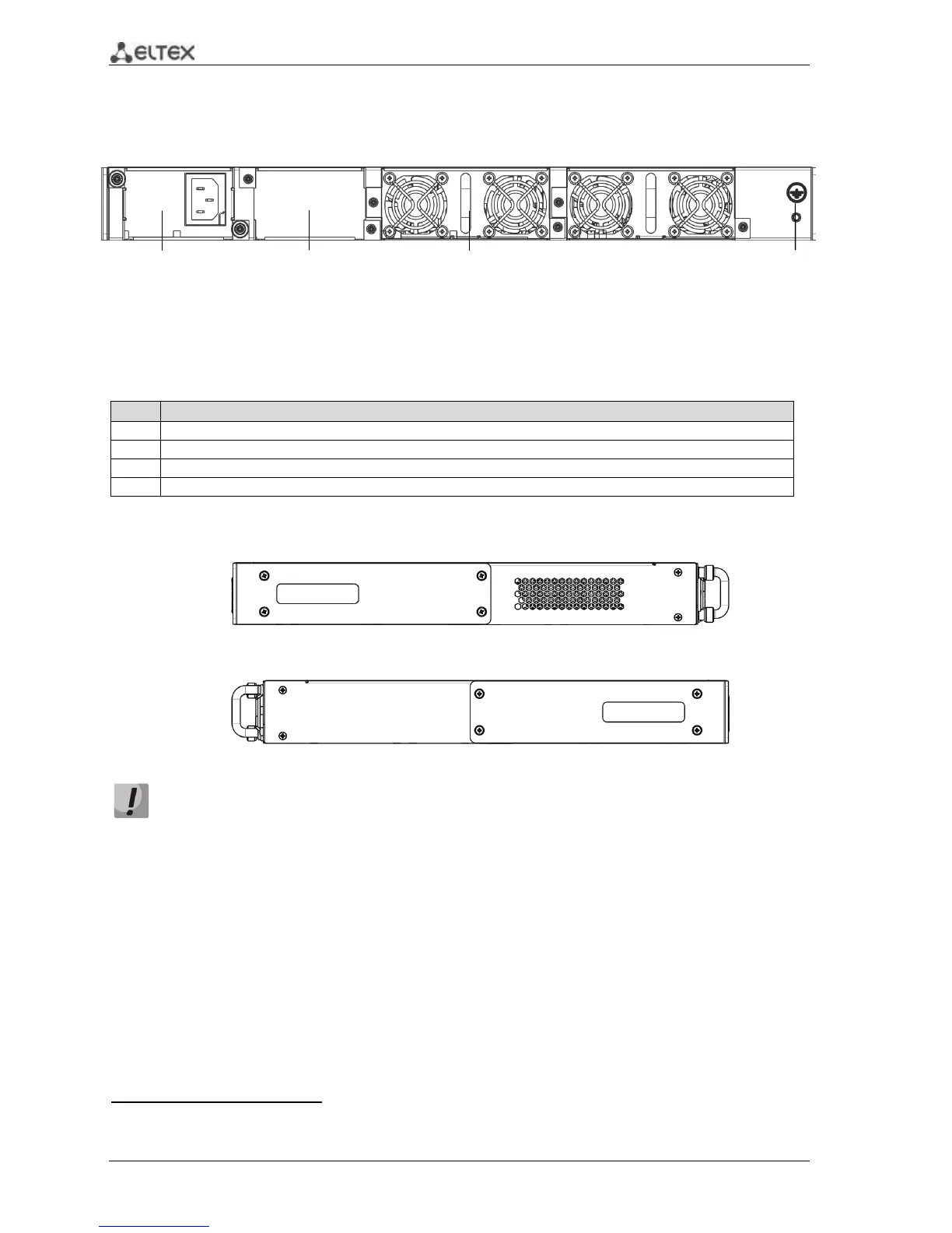
The back panel of ESR-1000/ESR-1200 is represented in figure 2.3
1
.
Figure 2.3 – Back panel of ESR-1000, ESR-1200
The list of connectors located on the back panel of ESR1000/1200 is described in Table 2.3.
Table 2.3 – Description of connectors located on back panel of ESR-1000, ESR-1200
Primary power supply source.
Place for reserve power supply installation.
Removable ventilation modules with hot swapping.
Device earth bonding point.
Side panel
Figure 2.4 - ESR-1000, ESR-1200 right-side panel
Figure 2.5 - ESR-1000, ESR-1200 left-side panel
Side panels of the device have air vents for heat removal. Do not block air vents. This may
cause components overheating which may result in terminal malfunction. You can find
recommendations on the device installation in 'Installation and connection' section in user
manual.
1
The picture shows router configuration with one AC power supply.

 Loading...
