ESR series routers 7
2.2. ESR-100 and ESR-200 designs
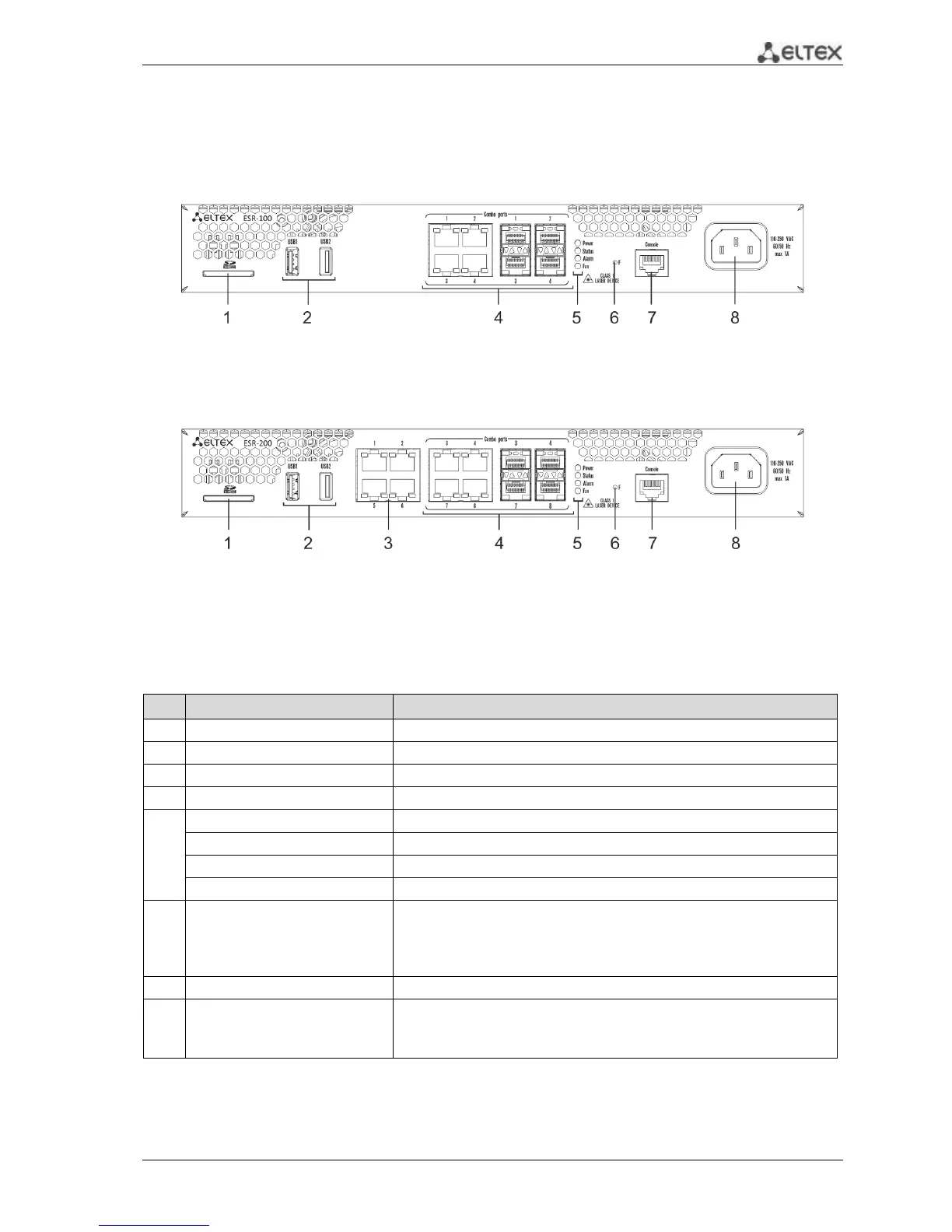
ESR-100 front panel
Figure 2.6 - Front panel of ESR-100
ESR-200 front panel
Figure 2.7 - Front panel of ESR-200
The list of connectors, light indicators and controls that are located on the front panel of ESR-100,
ESR-200 are described in the Table 2.4.
Table 2.4 – Description of connectors, light indicators and controls located on the front panel of ESR-100,
ESR-200
2 ports for USB-device connection.
4 ports for Gigabit Ethernet 10/100/1000 Base-T (RJ-45).
4 ports for Gigabit Ethernet 10/100/1000 Base-X (SFP).
Currency device indictor.
Existence and emergency level indicator of the device.
Emergency indicator of fans.
Functional key that reboots the device and resets it to factory settings:
– Pressing the key for less than 10 seconds reboots the device;
– Pressing the key for more than 10 seconds resets the terminal
to factory settings.
RS-232 console port for local device control.
110-250 VAC
60/50 Hz
max 1A

 Loading...
