4 ESR series routers
1. ANNOTATION
This guide coverages instruction of connection to power supply, factory device configuration and
basic ESR series router configuration recommendations (hereafter referred to as the device).
The guide is destined for technical staff that performs installation, configuration and putting the
device into operation.
2. DESIGN
The design of the devices is described in this section. The front, back, side panels' images are
represented, and the connectors, light indicators and controls are described below.
The device enclosed in metal case available for 19” form-factor rack-mount, case height 1U.
2.1. ESR-1000, ESR-1200 design
ESR-1200 front panel
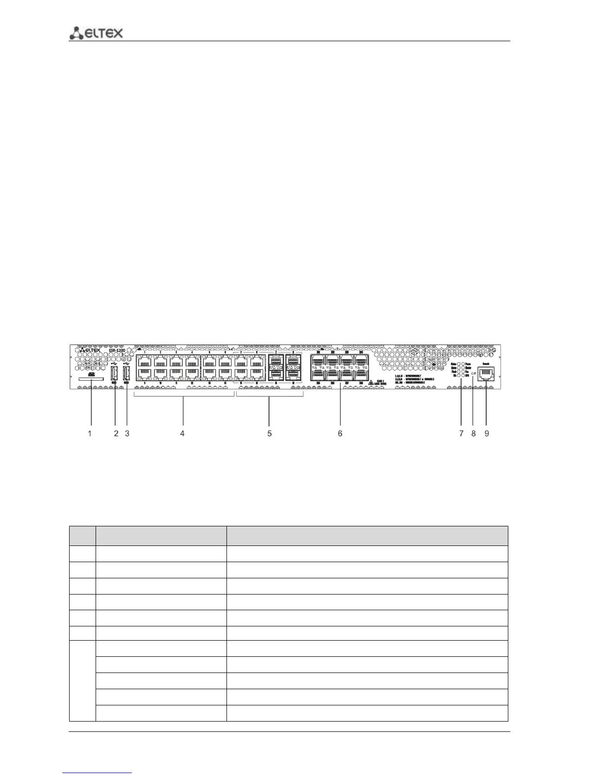
The front panel of ESR-1200 is represented in figure 2.1.
Figure 2.1 - Front panel of ESR-1200
The list of connectors, light indicators and controls that are located on the front panel of ESR-1200
are described in Table 2.1.
Table 2.1– Description of connectors, light indicators and controls located on the front panel of ESR-1200
 Loading...

