____________________________________________________________________________________
____________________________________________________________________________________
14 NTU Optical Network Terminals
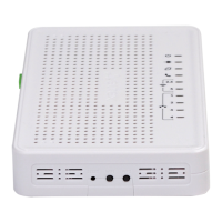
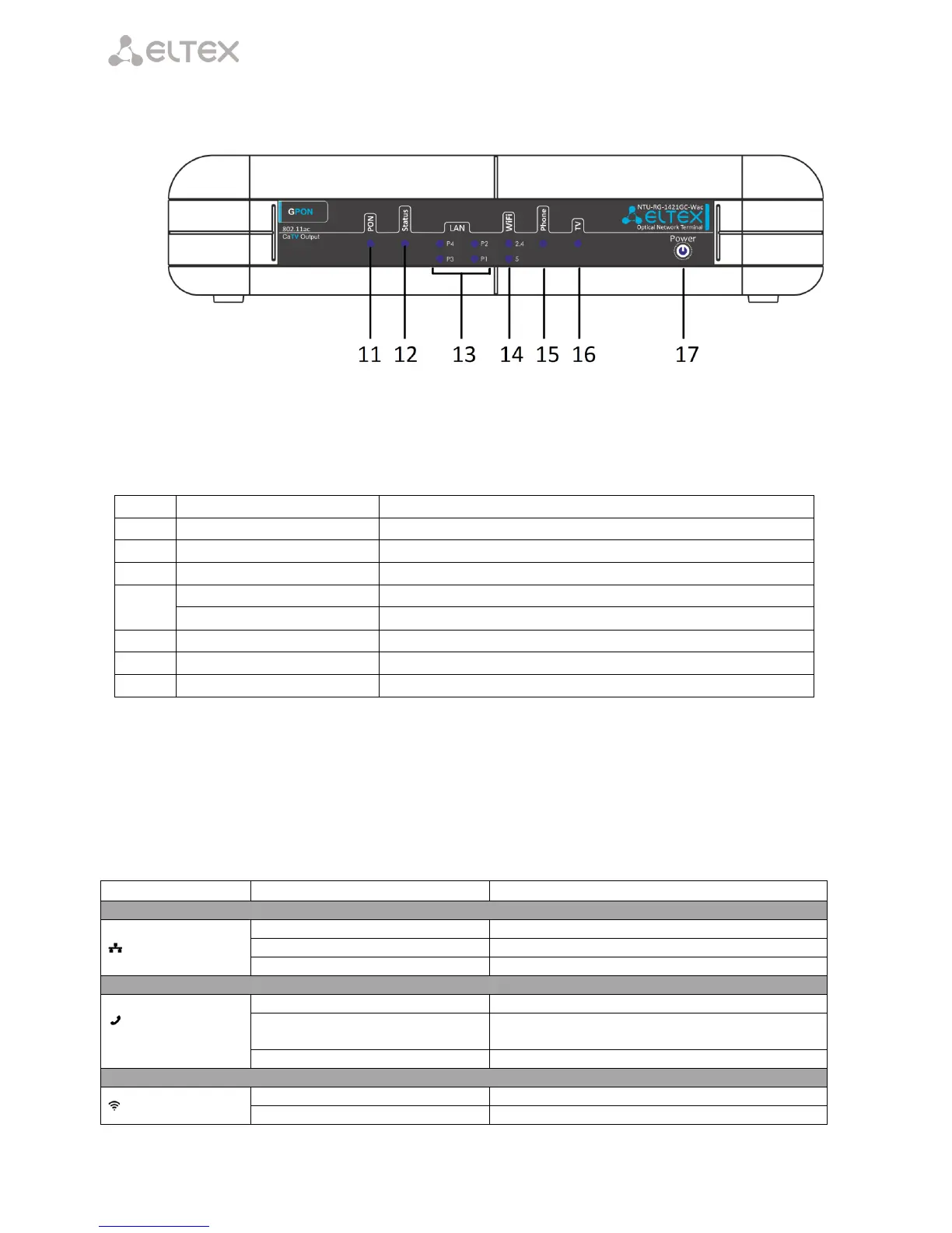
Fig. 5 shows the NTU-RG-1421GC-Wac front panel layout.
Fig. 5 –NTU-RG-1421GC-Wac front panel layout
Table 7 listed LEDs located on the device front panel.
Table 7 – Description of the LEDs located on the front panel
power and activity status indicator
configuration and hardware status indicator
Ethernet port activity indicator
Wi-Fi activity indicator for 2.4 GHz
Wi-Fi activity indicator for 5 GHz
FXS port activity indicator
2.6 LED Indication
2.6.1 NTU-RG-1421G-Wac, NTU-RG-1431G-Wac
LED indicators located on the front panel represent the current state of the device.
Possible states of the LEDs are listed in Table 8.
Table 8— Light indication of the device
10/100Mbps connection has been established
1000Mbps connection has been established
packet data transmission is in progress
port is not registered or authorization is not
completed on SIP server
 Loading...