________________________________________________________________________________
_________________________________________________________________________________
Universal Network Terminal TAU-72.IP/TAU-36.IP 21
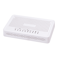
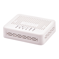
Fig. 4f - TAU-36.IP with AC power supply front panel appearance
Connectors, LEDs and controls located on the front panel of the device are listed in Table .
Table 2 – Description of connectors, LEDs, and controls located on the front panel
Connector for DC power supply with rated voltage 48VDC
~150 – 250 VAC, 50 Hz max 2A
Connector for AC power supply with voltage 150–250VAC, 50Hz
Device operation indicator
Optical interface SFP processing indicator. Lights green when optic
link is present
Line 1...18, 19…36, 37…54, 55…72
4 CENC-36M connectors for analogue phones connection (pin
designation is listed in appendix A)
3 x RJ-45 ports of Ethernet 10/100/1000 Base-T interfaces
RS-232 console port for local control of the device
Chassis for optical SFP modules of 1000Base-X Gigabit uplink
interface used for IP network connection
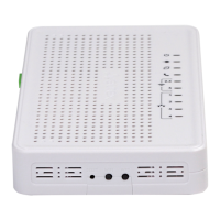
The layout of the device rear panel is shown on Fig. 5.
Fig. 5 - TAU-72.IP/TAU-36.IP rear panel appearance.
Grounding point is located on the rear panel of the device.
Connector pin designation is kisted in appendix A.
 Loading...