User Manual QT250 and QT800, ID 2021 2.0 July 2018
Remove the battery by sliding it out of
the frame.
Replace the battery and slide the new
battery into the frame.
Fasten the battery holding bracket with
the four M3 hex socket head screws by
turning them clockwise. Tighten the
screws to 1,2Nm and lubricate the
threads using Molykote 1000 or similar
lubricant containing MoS2. Make sure
that the grounding connectors are
placed as shown in the illustration
before tightening the screws. The
screws are circled red in the illustration.
Required equipment:
− 2,5mm Hexagon Key.
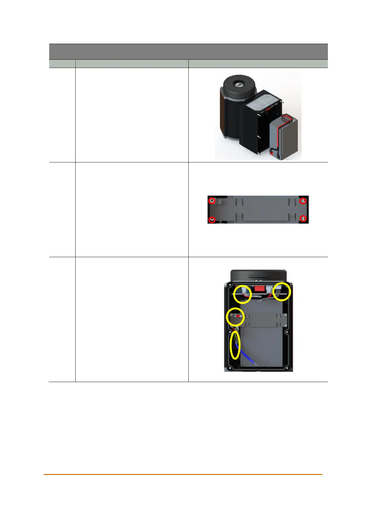
Hold the interface close to the actuator
and connect the connectors marked by
yellow circles in the illustration. The two
equal connectors are distinguished by
the color on the cable sleeve. The cable
with the blue sleeve connects to the
cable with the blue sleeve, and the cable
with the black sleeve connects to the
PCB.
 Loading...
