GB
17
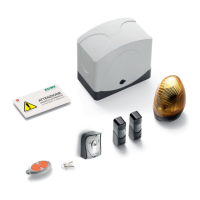
Fig. 2A
Fig. 2B
Fig. 2C
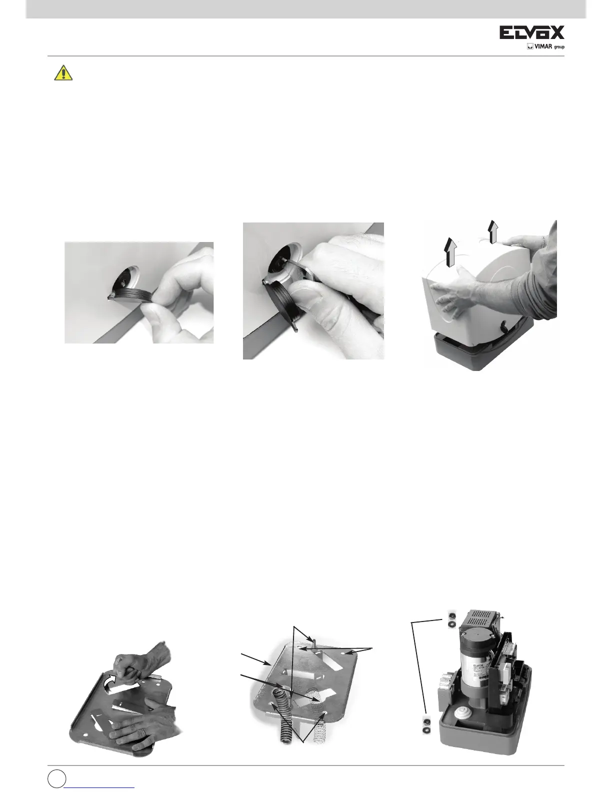
B
A
C
D
D
Fig. 3A
Fig. 3B
MECHANICAL INSTALLATION
For an automation correct operation the existing gate structure or the one to be carried out, must have the following features:
- The wheels of the gate are fixed in such a way as to provide gate stability, and are in good working order.
- The track is free, straight and clean along its entire length with compulsory limit stops fitted at the points of opening and closing.
- The upper guide is aligned with the track, the runners are intact and lubricated with a play of around 1 mm on each side to facilitate the slid-
ing of the gate.
- The gaps between the moving and fixed parts of the gate conform to national standards. If not, they should be fitted with a suitable protec-
tion system in compliance with the safety standards.
- The gate weight must not exceed 600 Kgs.
- Absence of closing mechanical locks.
It is suggested to effect the necessary interventions in order to guaranty the automation confidence and safety.
Actuator installation
1. Remove the lock tap (Fig. 2A) and insert the key (Fig. 2B). Remove the door lock.
2. Remove the plastic cover by light pressing on both sides (Fig. 2C).
3. To fix the motor reducer to the soil use the counter-plate Art. ZX16 (not supplied).
Site preparation
After selecting the site of gearmotor installation (to the right or left of the gate), it is possible to fix the motor with 2 plugs or the backplate can be used
in two ways:
1) Plate embedding (Fig. 3A - Fig. 3B)
2) Anchoring to ground by means of 4 expansion plugs (not supplied)
N.B. The backplate must be embedded or secured strictly observing the measurements specified in Fig. 3 to guarantee the correct meshing of the pi-
nion of the gearmotor with the rack.
Plate embedding
a. Fold the 3 clamps Fig. 3
b. Position the backplate so that the central clamp is towards the pinion of the gearmotor (and towards the rack) Fig. 3B detail A.
c. Insert the two M8x30 screws supplied, in the square holes and secure by means of the nuts to fix in the panel, Fig. 3B detail C.
d. Use the flexible hoses, required for connection cable routing (accessories - electric power supply).
Route the hoses through the two holes, Fig. 3B detail B.
The hoses should protrude by approx. 5 cm from the holes in the plate.
d. Embed the backplate in a perfectly level position.
Fixture with expansion plugs
Prepare a flat solid concrete slab of sufficient size to cover the backplate.
N.B. Make a slab that protrudes by a few centimetres from ground level to protect the gearmotor from the effects of build-up or flowing rainwater.
- Follow points c and d.
- Fix the backplate with 4 anchor plugs (M8x120mm not supplied Fig.3B detail D) and tighten the screws using the washers.
(the plugs enable height adjustment of the plate).
Gearmotor fixture
- Lay the cables
- Position the gearmotor in observance of the measurements specified in Fig. 1. Place the gearmotor on the backplate so that the screws, M8x30, enter
the two fixing holes and secure the nuts with flat washer and toothed washer, see Fig. 3C detail E.
Fig. 3C
E
 Loading...