24
GB
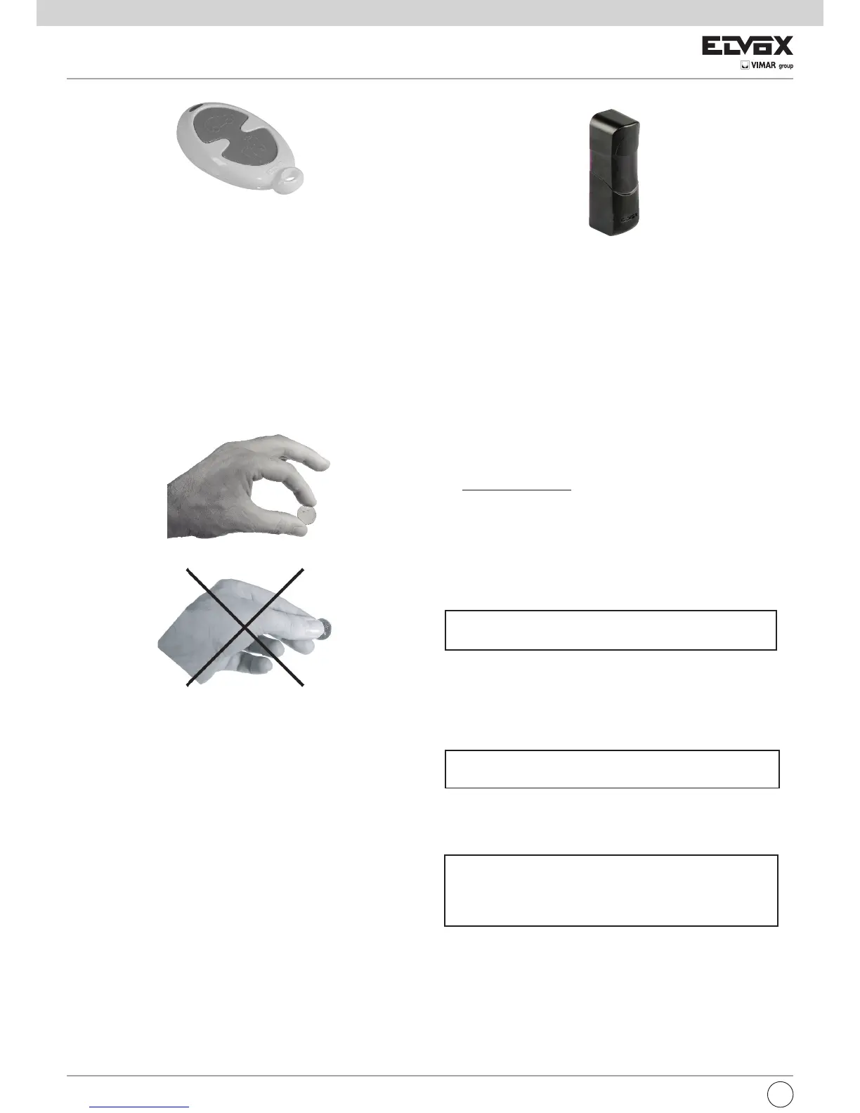
PHOTOCELLS ART. EFA1
Photocell synchronized version for surface flush-mounting with possibility
to turn the circuit 180°. Consisting of receiver (RX) and transmitter (TX) with
modulated infrared rays.
NOTE: use for backscattering the installation on non-rigid surfaces subject
to vibrations is forbidden.
Technical specifications:
- Power supply: 12 V D.C./A.C. with jumper, 12-24, inserted (limits 10-18
V A.C.) 24 V D.C./A.C. without jumper, 12-24 (limits 18-32 V A.C.)
- Max. absorption: at 12V: Rx 46mA, Tx (min) 65 mA, Tx (sync.) 37 mA at
24V: Rx 55mA, Tx (min) 54 mA, Tx (sync.) 45 mA
- Relay capacity: 1A at 24 V D.C. / 120 V A.C.
- Response time:< 30 ms.
- Operating temperature: -20°C ¸ +55°C
- Detection angle: Rx ± 20°C
- Radius angle emitted: Tx ± 12°C
- Protection rating: IP55
- Maximum range: 15 m
NOTE: The range may decrease by 50% when there is atmospheric phe-
nomena: fog, rain, dust, etc.
Dimensions (wxhxd): 34x113x36 mm
CONNECTIONS:
1) Select the photocell supply voltage by operating on the jumper JP12V
for the supply voltage selection.
The 12/24V DC/AC choice must be made according to the voltage avai-
lable in the control unit.
JP 12 with jumper inserted = 12V DC/AC supply voltage
JP 12 without jumper = 24V DC/AC supply voltage
2) If the two transmitters (TX) are installed one close to the other, the ray
of one could interfere with the ray of the other. in this case the correct
operation cannot be guaranteed. To avoid this problem, if the alterna-
ted current supply voltage is available, it is possible to use the synchro-
nism system which allows the two pairs of photocells to operate
alternatively. To activate the synchronism function remove the "sync"
jumper on the transmitter (TX).
Jumper "sync" inserted = normal operation
Jumper "sync" not inserted = synchronism function
3) Carry out the electrical connection according to the required function,
as per the technical features (see Fig. 7).
The bicolour LED present on the receiver allows you to verify the cor-
rect aligning between the RX and TX.
LED Meaning
Switched off No supply voltage
Red Presence of obstacle, wrong aligning
Flashing light Wrong aligning
Green Perfect aligning
4) Once the photocell installation has been carried out, check the opera-
tion interrupting several time the beam (infrared ray);
Check the RX red LED lighting and the relay switching.
5) Once the final check up has been accomplish, position the front part.
INSTALLATION:
1) Insert a screwdriver into the slot made in the central bottom side of the
cover (see Fig. 8).
2) Secure the bottom of the photocell to the wall, with the aid of plugs,
trying to get the best alignment.
PHOTOCELL ROTATING 180° FROM WALL SURFACE
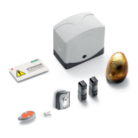
2 ROLLING CODE RADIO CONTROL CHANNEL
RADIO CONTROL ART. ETR2
For every radio control a different code is saved in series.
TECHNICAL FEATURES
Frequency: 433,92 Hz
Battery: 2x3V (CR 2016)
Range: 50
¸100 m
Code combinations: 4.294.967.296
Dimensions: 71x38x14 (mm)
Weight: 16gr.
BATTERY REPLACEMENT
Remove the fixing screw and open the cover. Remove the battery and
replace it taking account the polarity.