18
GB
Fig. 4B
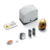
Fig. 4A
2 mm obtained at the end of the adjustment pro ce du re
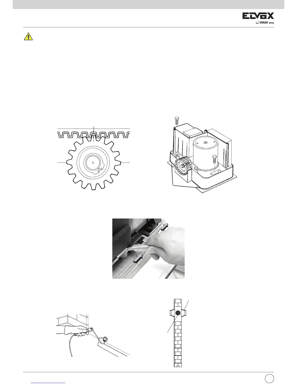
Shim brackets
MANUAL RELEASE
In case of mains failure, the back-up battery (option) guarantee the automation operation for a short period. If the battery is flat or not used release the
motor manually by opening the cover with proper key (see Fig. 1A, 1B, 1C) and turn the release lever 180° counter-clockwise (Fig. 5). Close the cover
again.
Fig. 5
INSTALLATION OF MECHANICAL LIMIT STOPS
At the open and close positions of the sliding gate, mechanical limit stops must be fitted which are able to stop the movement of the gate during both
opening (Fig. 6A) and closing (Fig. 6B). Always follow the recommendations of the various relevant standards.
Fig. 6A
Fig. 6B
BOUCHON
BRACKET
GATE LIMIT STOP
FRONTAL VIEW
Mounting the rack:
1 - Close the gate completely.
2 - A play of 2mm must be ensured between the pinion and the rack for the whole length of the gate (Fig. 4A). To do so position the spacers (provided)
as shown in Fig. 4B and the gearmotor.
NOTE: This operation is very important for the motor operation and its dwell time. In fact it is convenient that the gate load not to lie on the pinion, be-
cause it could damage the automatic system.
3 - Release the motor pulling rightward the mechanic release lever (Fig. 5).
4 - Lean the rack on the pinion so that its end, once it has been fixed, coincide with the end oth the door. Mark the holes position.
5 - Make the gate run all its length repeating the procedure in order to find the fixing or soldering points.
6 - To use the rack in nylon, bore the door with a 5.25mm drill, and fix the rack with 6,3mm selfthreading screws (supplied with the rack). To use the zinc
plated rack, solder the couplings and fix the rack with the M8 screws (supplied with the rack) preceded by a washer.
7 - Once the rack has been fixed, loosen the screws fixing the actuator and remove the spacers.
8 - Reposition the motor so that the pinion is exactly superposed by the rack.
The result must be the same as that shown in Fig. 4A.