GB
19
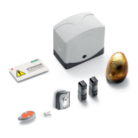
Fig. 7C
Fig. 7B
Fig. 7A
A
ELECTRICAL INSTALLATION
Each device must be expertly installed, following the enclosed instructions and above all must be set up by qualified Elvox Automation Division approved
personnel in accordance with the standards in force in each individual country.
Follow the enclosed instructions for the connection of the cables to the electronic control card. Keep in mind that:
1 -
The control central unit is powered by a security transformer. To connect the supply voltage to the automatic gate system unscrew the 4 screws
and remove the cover (Fig. 7A), enter the 230V c.a. mains cable as per point A Fig. 7B and connect it to terminal block as per Fig. 7C.
2 - The recommended cross-section of the connecting cables for the motor is 1.5mm
2
.
3 - The gate’s earthing device must conform to the standards in force. The manufacturer will not accept any responsibility for damage arising from neg-
ligence in this respect.
4 - In accordance with the European safety standard, it is recommended that an external twopole switch is installed in order to be able to disconnect
the power supply during maintenance to the gate and to disconnect the terminal of the card supply voltages.
Mains
Transformer
Fuse 2AL250V (Mains: 230V, 240V)
Fuse 4AL250V (Mains: 110V, 117V, 125V)
CONTROL UNIT TERMINAL DESCRIPTION
No. of terminals Description Function
1 2 Motor 1 Motor supply voltage: motor 1 12V DC
3 4 Channel 2 Channel 2 output selectable by parameter
12VDC 1W timed voltage or pedestrian function.
4 5 AUX Output with supply voltage 12V DC 1W IN or warning light function.
6 7 (-)12 (+)12 Photocell power supply 12V DC 500 mA max.
8 9 LAMP Flashing light 12V DC 5W max.
10 11 COM - AP/CH Input for selector or push-button, NO contact, OPEN/CLOSE
10 12 COM - PED Input for selector or push-button, NO contact, pedestrian opening
13 14 COM - STOP Input for STOP function selector or push-button, NC contact
13 15 COM - FOT Photocell input, NC contact
13 16 COM - STPA Input for opening (internal) photocell or sensitive edge, NC contact
(-) ANT Aerial Aerial wire or cable connection
CN4 Encoder Magnetic encoder
ELECTRONIC CARD EC10
THE electronic card, Art. EC10, is suited to control an actuator for sliding gates, ES series, with a 12 Volt direct current motor.
This card has high quality standards and is equipped with a gate movement control system with an ENCODER to ensure conformity with the requirements
of the directives on electromagnetic compatibility, CE marking and current safety standards. The gate is opened/closed by it slowing down, its speed and
the amperometric consumption of the motor are constantly monitored, and the motion is reversed if there is an obstruction.
ELECTRICAL INSTALLATION
The control unit EC10 is powered at 230V (117V for the /117 version and 240V for the /240V version), the mains voltage is protected by a 4A fuse. The board
is powered with 12V AC via a safety transformer with double insulation (EN61558).
The actuators and controls are powered with 12V DC and the outputs are protected by two fuses: a 15A fuse (F1) for the actuators and a 3.15A fuse (F2)
for the accessories. Operating temperature -20 to +55°C.
Being a low-voltage board, the metal structures connected to it must not be earthed since the power supply is SELV isolated.
For cables of more than 15 metres in length, use 2x4mm
2
wires.