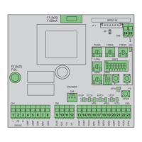
Key:
1- Removable terminal for the power line, flashing light and electric motor
2- Removable terminal for 24 Vdc outputs
3- Removable terminal for safety and control inputs
4- LED for input diagnostics
5- APCH control sequential button
6- Buttons for programming the travel and remote controls
7- Dip switches for programming functions
8- Trimmer for adjustments
9- LED for programming diagnostics
10- Removable aerial connector
11- Radio module
12- Protection fuse for 24 V output and control logic (630 mA)
13- Protection fuse for motor output, transformer and flashing light (5 A)
14- Encoder connector
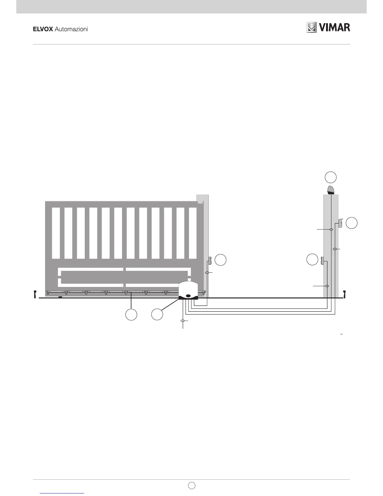
3 - Electrical wiring harnesses:
System set-up
Key:
1 - Photocells
2 - Selector switch
3 - Flashing light
4 - Gear motor
5 - Rack
Fig. 2