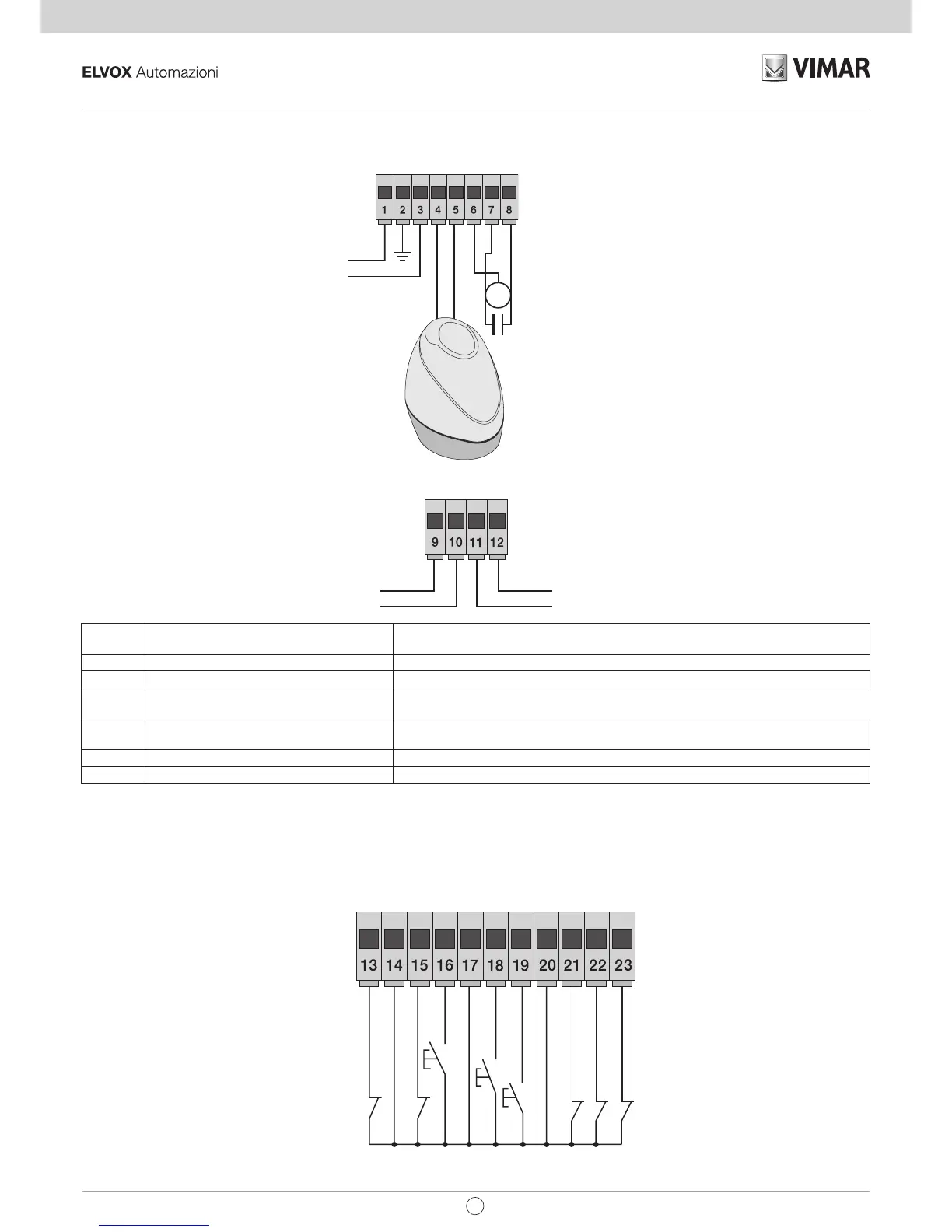
3.1- Wiring for power line, flashing light and electric motor:
3.2- Wiring for 24V outputs:
Terminal
number
Description Function
1-2-3 Power supply line 230/120 Vac power line (1 = phase / 2 = ground wire / 3 = neutral)
4-5 Output for flashing light Output for flashing light (230/120 Vac max 60 Watt)
6-7-8 Output for powering the electric motor Output for powering the electric motor (6 = common / 7 = opens / 8 = closes) the
capacitor is connected in terminal 7 and 8 in parallel with the electric motor
9-11 Second radio channel or photo-test output Second radio channel or photo-test output (can be selected with dip switch 1-3 and 9 =
GND / 11= +24 Vdc max 120 mA)
10-11 Gate movement warning output Gate movement warning output (10 = GND / 11 = +24 Vdc max 120 mA)
11-12 24 Vdc output 24 Vdc output to power photocells and accessories (11 = GND / 12 = +24 Vdc 300mA)
3.3- Input wiring:
The control panel is supplied with non-jumpered normally closed safety inputs (STOP, FOTO, STPA), add a jumper between the common (COM) and
input you do not intend to use
-
-
+
-
24Vdc output to power photocells and accessories
Second radio channel or photo-test output
Output for viewing gate movement
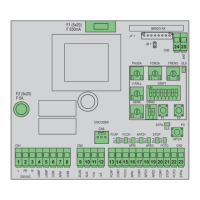
2CAN AUX +24V GND
Fig. 4
Fig. 5
The sum of the absorptions of the 2CAN, AUX and -VA outputs must not exceed 500 mA