EM TEST VDS 200 Series
Manual for Operation V 5.19 30 / 57
Test Equipment
Construction
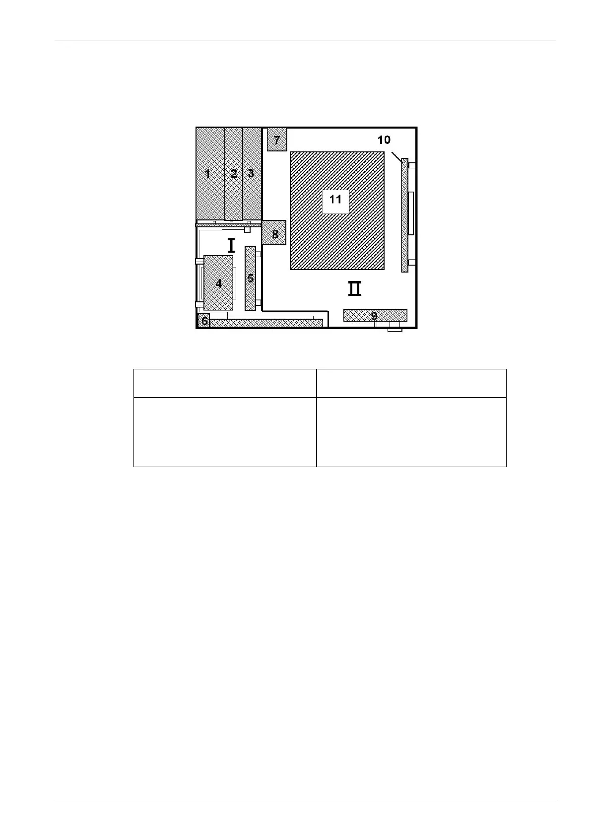
The Voltage Drop Simulator VDS 200 is built in a 19" housing and is divided into two parts, the control unit and the
power electronics. The 100A type is designed in a small rack on wheels.
1 Power supply
2 Interface board
3 Processor board
4 Transformer
5 Filter board
6 Keyboard / LCD display
7 Power supply
8 Current sensor
9 Front-panel board
10 Control for Amplifier
11 Amplifier design depends on model
Control unit
The control unit is based on a microprocessor system and a driver board which includes a galvanic decoupling
between the control unit and the power electronics. The firmware for controlling the system is stored in two
EPROM’s. The control unit is built up by 3 boards, the power supply, the micro-controller board and the interface
board.
Power supply unit
The power supply unit supplies voltages of +/- 15V, + 5V, + 24V for all other modules of the simulator. The unit is
fused on the back of the device in the power supply socket.
Micro-controller unit
This unit controls the entire functions of the power supply simulator and simultaneously organizes the data
transfer via the serial RS 232 or parallel IEEE interface.
The desired test parameters are preselected via the function keys or the knob (incr./decr).
I / O Controller
All control parameters entered via the keyboard or the interfaces are interpreted by the I/O controller. In addition
this print contains the control of the power electronics as well as the optical separation between control circuits
and power electronic.
LED
Two LED’s mounted on the front panel show if a channel is active or not. The LED of an active channel is lighted.
During mode V the LED display switches from one channel to the other.
 Loading...