EasyManua.ls Logo

EM TEST VDS 200 Series User Manual

EM TEST VDS 200 Series
57 pages
To Next Page IconTo Next Page
Page #1 background imageLoading...
Page #1 background image
M a n u a l
f o r O p e r a t i o n
VDS 200 series
Voltage Drop Simulator pulses 2b, 4
VDS 200N10, N15, N30 N50
VDS 200N100, N150 N200
VDS 200N30.1 N50.1
VDS 200N100.1 N100.2 N100.3 N100.4
N100.5 N100.6
VDS 200N150.1
VDS 200N200.1 N200.2 N200.3 N200.4
RDS 200N
Testing of electronic modules in 12V/24V or 42V supply
systems.
The VDS 200Nx is a low frequency amplifier. It simulates the
battery power supply of a vehicle and complex power supply
distortions in the power range up to 12'000W. A lot of different
waveforms are integrated as standard such as pulse 2b and
pulse 4 required in ISO 7637.
ISO 7637
SAE J1113
Manufacturer spec
GM, Ford, Chrysler,
BMW, VW, PSA,
Renault, Fiat ....
5.19 / 03.09.2013
the benchmark for emc
5.18 / 17.06.2013
UserManual-VDS200Nx-E-V519.doc
03.09.13

Table of Contents

Question and Answer IconNeed help?

Do you have a question about the EM TEST VDS 200 Series and is the answer not in the manual?

EM TEST VDS 200 Series Specifications

General IconGeneral
BrandEM TEST
ModelVDS 200 Series
CategoryAmplifier
LanguageEnglish

Summary

VDS 200 Series Introduction

Product Overview

Describes the VDS 200Nx as a low frequency amplifier for simulating battery power supply distortions.

Operating Functions

Front View

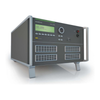
Explains the front panel layout, including display, function keys, and controls for operating the VDS 200.

Operation

Change of Parameters

Guides on changing parameters, starting, stopping, and continuing test routines with the simulator.

Test Equipment

Overvoltage Protection

Introduces the overvoltage protection system, its purpose, and availability on VDS models.

Function

Describes the crowbar switch and controller functionality of the overvoltage protection.

Protection Levels

Lists selectable protection levels, switch-off thresholds, maximum overvoltage, and response times.

Level settings by the user

Provides instructions for user level settings and illustrates typical protection behavior with oscilloscope plots.

Typical protection behavior

Illustrates the typical behavior of the overvoltage protection system using oscilloscope screenshots.

Maintenance and Calibration

Calibration and Verification

Details factory calibration, period guidelines, accessory calibration, and in-house verification procedures.

Related product manuals