EM TEST VDS 200 Series
Manual for Operation V 5.19 51 / 57
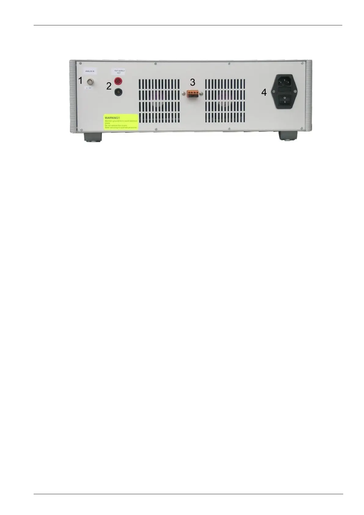
Rearside RDS 200
1 Analogue input 0 - 10V
2 Test Supply output rearside
3 Connector
4 Power On switch with fuse
1 Analogue input 0-10V
The internal amplifier can be controlled by an external signal generator.
The input signal range is 0-10V in the frequency range of 0-5kHz.
The output power (EUT test supply) than would result in 0-16V.
2 Test supply output
At this output the generator can be loaded with the maximum current of 10A. This output is also used for the
internal wiring in a complete rack system installation.
3 Connector
This connector must be in this position and should not be changed .
4 Power On switch
230V or 115V system: The Power On switch includes also the power mains fuses (2 x 4A T) and filter unit.
 Loading...