EM TEST VDS 200 Series
Manual for Operation V 5.19 31 / 57
Arbitrary Wave Simulator
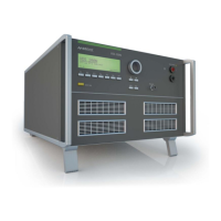
The following diagram shows the principal layout of the amplifier. By controlling the semiconductor switches
nearly any waveshape can be simulated.
The amplifier is used generally as a high power dc supply for feeding the equipment under test.
Additionally with the built in waveform generator arbitrary waveforms which are required in many standards can
be generated, such as pulse 4 and pulse 2b of ISO, sine wave sweeps and so on.
The unit can also be used as a high power amplifier up to 50kHz bandwidth, see the limitations. For this purpose
the unit can be controlled by an external signal generator at the BNC input (0-10V). This input is located at the
rear panel of the instrument.
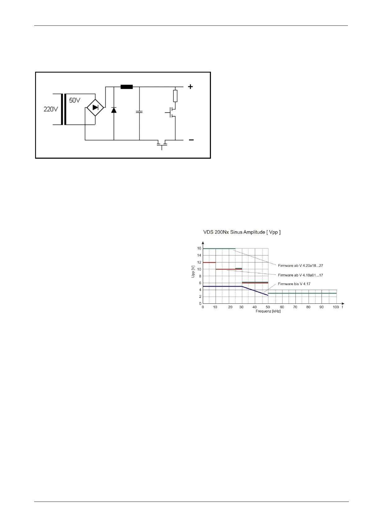
Frequency behavior
Firmware from version 4.20a18...27 manufactured. 2007 or later
16Vpp up to 25kHz
10Vpp up to 30kHz
6Vpp up to 50kHz
Firmware version 4.18a01...17 and higher
12Vpp up to 10kHz
10Vpp up to 30kHz
6Vpp up to 50kHz
Firmware up to version 4.17
5Vpp up to 30kHz
>30kHz linear decrease to 3.5V at 50kHz (see diagram)
 Loading...