4
Mainboard connections
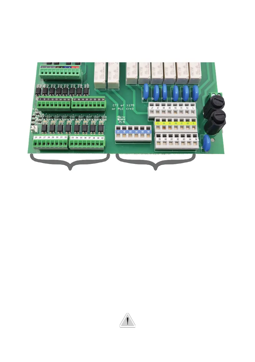
Unplug CONTROLLER from main power supply then perform connections by following the picture below.
For easy understanding the board has been divided into two parts: I/O connections and Power - Relays connections.
For mA outputs and optionals connections refer to page 35.
Fuses:
F1: Main Power Fuse (6,3A T)
F2: CONTROLLER Fuse (3.15A T)
S1(+) - S2(GND): Standby
PEF: Connector for PEF LIGHT ALARM
FOUT: Remove jumper to disable L(LIVE) from RELAYS OUTPUTS
Power and Relays Connections:
L(Live) - E(Earth) - N(Neutral): Main power supply 230VAC (85-264VAC, 50/60Hz) or 24VAC* 50/60 Hz *see controller’s label
LF (LIVE FUSE PROTECTED): Live input for motorized EV
41(N.C. contact) - 42(Common) - 43(N.O. contact): Free of voltage contact (max insulation 250V) RELAY n.1
44(N.C. contact) - 45(Common) - 46(N.O. contact): Free of voltage contact (max insulation 250V) RELAY n.2
47(L) - 53(E) - 59(N): Setpoint RELAY n.3
48(L) - 54(E) - 60(N): Setpoint RELAY n.4
49(L) - 55(E) - 61(N): Setpoint RELAY n.5
50(L) - 56(E) - 62(N): Setpoint RELAY n.6
51(L) - 57(E) - 63(N): Setpoint RELAY n.7
52(L) - 58(E) - 64(N): Setpoint RELAY n.8
Power and Relays ConnectionsI/O Connections
Warning: Connections must be perfomed by qualified and trained personnel only
F1
F2
1 2 3 4 5 6 7 8 S1 S2
9 10 11 12 13 14 15 16 17 18 19 20 21 22 23 24
25 26 27 28 29 30 31 32 33 34 35 36 37 38 39 40
47 48 49 50 51 52 L
53 54 55 56 57 58 E
59 60 61 62 63 64 N
LF
PEF
FOUT
41 42 43 44 45 46