42
Appendix - Adding / Removing probe modules / optionals / mA
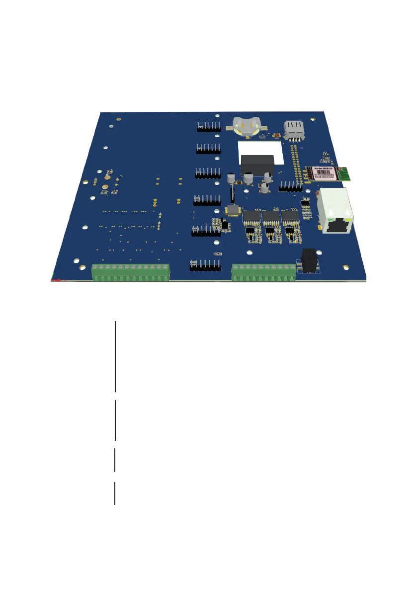
To remove or add a new probe’s module, rst disconnect the controller from main power supply then remove the white
front cover by pulling it. Unscrew the 8 screws and open main panel as shown in gure p.38 to gain access to modules.
Install the new module to any slot available or remove unwanted modules by unscrewing it from main board. Slots order
shown on the display is progressive from left to right.
1 2 3 4 5 6 7 8 9 10 11 12
13 14 15 16 17 18 19 20 21 22
SLOT 6
SLOT 5
SLOT 4
SLOT 3
SLOT 2
SLOT 1
I/O Connections:
1: mA Output n.6 n/a
3: mA Output n.5
5: mA Output n.4
7: mA Output n.3
9: mA Output n.2
11: mA Output n.1
2 / 4 / 5 / 8 / 10 / 12: GND
13: GND (black wire)
14: 12VDC (red wire)
15: -RS485 (B) (green wire)
16: +RS485 (A) (white wire)
17: -RS485 (B)
18: +RS485 (A)
19: GND
20: -RS485 (B)
21: +RS485 (A)
22: GND
mA Outputs
LEVEL LASER
SENSOR COMMUNICATION BUS
COMMUNICATION PORT
LEGACY CONTROLLERS (LD - LDS SERIES)
COMMUNICATION PORT
Centurio PRO - Centurio POOL - LDOSIN SERIES - MODBUS