163
User Defined Motors
Encoder Electrical Interfacing
Each of the encoder signals is received by a differential receiver to minimize the noise
susceptibility and to increase frequency bandwidth. This requires two wires for each logical
signal. (i.e., signal A requires channel A and A/, etc.).
For optimum performance these signals should be generated by an encoder with a line driver
output. Encoders which supply only single ended output signals will require some interfacing
circuitry.
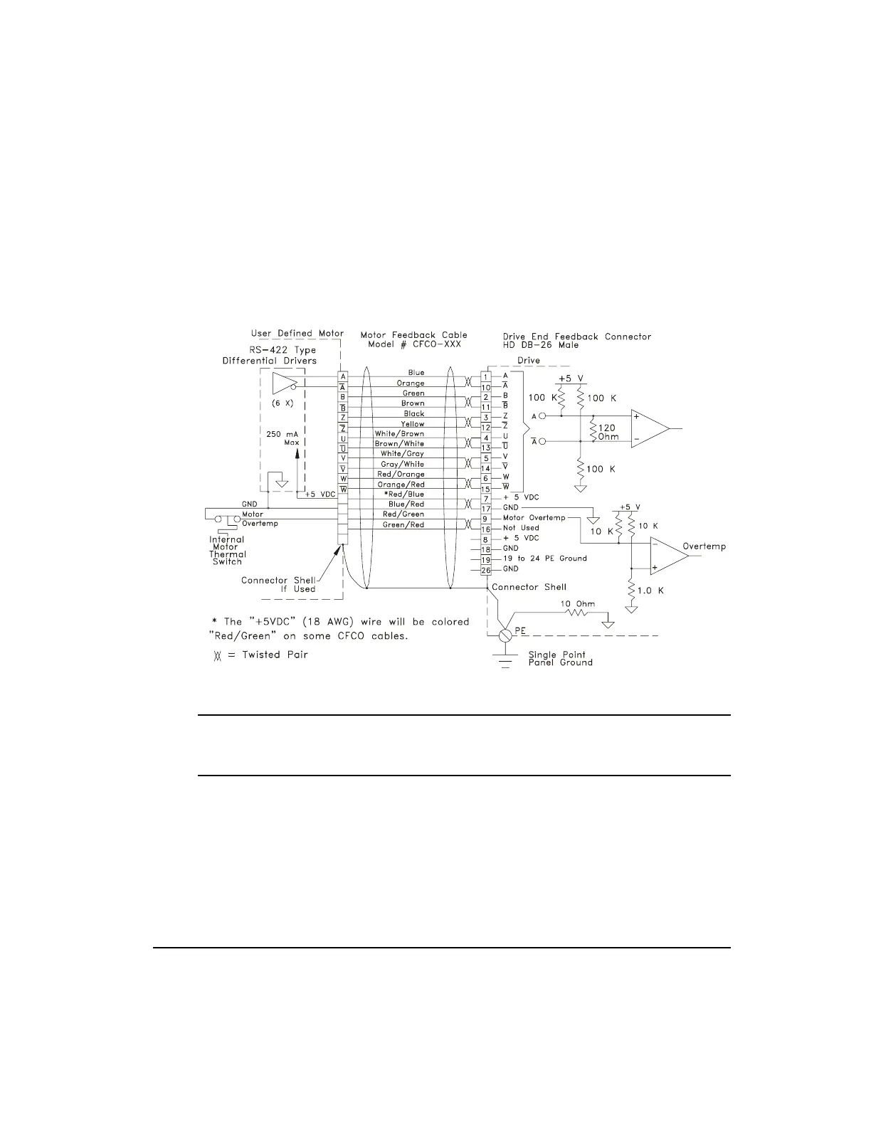
Figure 119: User Defined Motor Differential Feedback Connections
Note
The maximum current available out of the drive encoder +5 volt supply connection is 250
mA.
Artisan Technology Group - Quality Instrumentation ... Guaranteed | (888) 88-SOURCE | www.artisantg.com
 Loading...