22
EN Drive Installation Manual
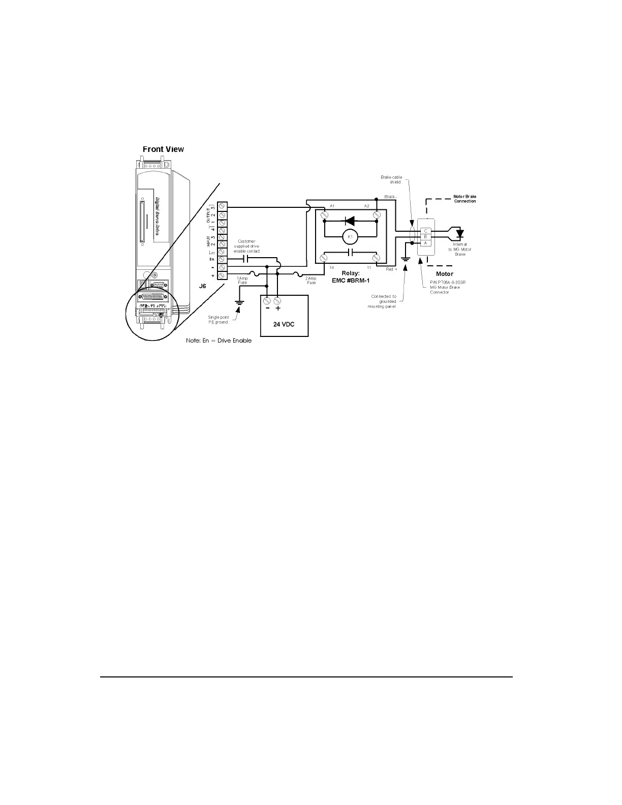
Figure 17: EN Brake Wiring Diagram using the I/O Connector
Input/Output and Drive Enable Wiring
Drives are equipped with five optically isolated input lines (one is dedicated to a drive enable
function) and three optically isolated output lines. They are designed to operate from a +10
to 30 VDC source. All inputs and outputs are configured as sourcing. You are responsible for
choosing a load that will limit each output’s current to less than 150 mA.
Artisan Technology Group - Quality Instrumentation ... Guaranteed | (888) 88-SOURCE | www.artisantg.com
 Loading...